Orange County Fire Authority
Community Risk Reduction
1 Fire Authority Road, Building A, Irvine, CA 92602 www.ocfa.org 714-573-6100
Fire Master Plans
for Commercial &
Residential Development
Guideline B-09
Serving the Cities of Aliso Viejo • Buena Park • Cypress • Dana Point • Garden Grove • Irvine • Laguna Hills • Laguna Niguel • Laguna Woods
Lake Forest • La Palma • Los Alamitos • Mission Viejo • Rancho Santa Margarita • San Clemente • San Juan Capistrano
Seal Beach • Santa Ana • Stanton • Tustin • Villa Park • Westminster • Yorba Linda • and Unincorporated Areas of Orange County

Fire Master Plans for Commercial & Residential Development: B-09 February 23, 2021
1
Fire Master Plans for
Commercial & Residential Development
TABLE OF CONTENTS
PURPOSE ....................................................................................................................... 2
SCOPE ............................................................................................................................ 2
Definitions................................................................................................................................ 2
SECTION 1: PLAN SUBMITTAL REQUIREMENTS ...................................................... 4
SECTION 2: FIRE ACCESS ROADWAYS ..................................................................... 5
Loading ................................................................................................................................... 5
Number Required .................................................................................................................... 6
Location ................................................................................................................................... 7
Width ....................................................................................................................................... 8
Parking Restrictions ................................................................................................................. 8
Vertical Clearance ................................................................................................................... 9
Grade ...................................................................................................................................... 9
Turning Radii ........................................................................................................................... 9
Dead-end Access Roadways ................................................................................................... 9
Bridges .................................................................................................................................... 9
Median Breaks ........................................................................................................................ 9
Continuity ................................................................................................................................ 9
SECTION 3: FIRE ACCESS ROADWAY IDENTIFICATION ........................................ 10
SECTION 4: PREMISES IDENTIFICATION ................................................................. 11
SECTION 5: OBSTRUCTIONS TO EMERGENCY VEHICLE ACCESS ...................... 12
Clear Width ............................................................................................................................ 12
Turning Radii ......................................................................................................................... 12
Setbacks ............................................................................................................................... 13
Manually Operated Gate and Barrier Design ......................................................................... 13
Electrically Operated Gates and Barriers ............................................................................... 13
SECTION 6: RESIDENTIAL TRACT DEVELOPMENTS .............................................. 15
SECTION 7: ENGINEERED ALTERNATIVE FIRE APPARATUS ACCESS ............... 18
SECTION 8: HYDRANT AND WATER AVAILABILITY REQUIREMENTS ................. 19
Water Availability ................................................................................................................... 19
Hydrants ................................................................................................................................ 20
SECTION 9: ACCESS TO STRUCTURES ................................................................... 22
Hose Pull ............................................................................................................................... 22
Access Walkways .................................................................................................................. 23
Path of Travel Obstructions ................................................................................................... 23
Key boxes and Key switches ................................................................................................. 24
Access to interior courtyards.................................................................................................. 26
SECTION 10: ACCESS DURING CONSTRUCTION ................................................... 28
Lumber Drop Inspection ........................................................................................................ 28
Temporary Fire Access Roads .............................................................................................. 29
Phased Access ...................................................................................................................... 30
INDEX OF ATTACHMENTS ......................................................................................... 32

Fire Master Plans for Commercial & Residential Development: B-09 February 23, 2021
2
Fire Master Plans for
Commercial & Residential Development
PURPOSE
The effectiveness of emergency response and firefighting operations is directly related
to the proper installation and maintenance of fire access roadways, the proper sitting of
hydrants, adequate water supply, and access to structures. This document is a general
guideline pertaining to the creation and maintenance of fire department access
roadways, access walkways to and around buildings, and hydrant quantity and
placement as required by the 2016 California Fire and Building Codes (CFC and CBC)
and as amended by local ordinance. This guideline includes requirements for:
Plan submittal
Fire access roadway design
Fire lane identification
Premises identification
Fire lane obstructions
Access for residential development
Alternative engineered fire access
systems
Access requirements in wildfire risk
areas
Hydrant quantity, spacing,
placement, and identification
Water availability and fire flow
Access to structures
Access during construction
Fire Safe Regulations for State
Responsibility Areas (SRA) and Very
High Fire Hazard Severity Zones in
Local Responsibility Areas (LRA)
SCOPE
These guidelines apply to new, remodeled, reconstructed, or relocated residential or
commercial structures and developments to which emergency response may be
necessary. The information contained in this document is intended to assist the
applicant in attaining compliance and to ensure that privately owned roadways
necessary for emergency response purposes will be available for use at all times.
Some of the issues discussed within this document may be covered in more detail
through other OCFA guidelines, as referenced. Areas of particular importance and
requirements that are commonly overlooked on fire master plan submittals have been
identified with a black arrow in the left margin. Items available on the OCFA website
(www.ocfa.org) will be identified by underlining.
For projects located in State Responsibility Areas (SRA) or in Local Responsibility Area
Very High Fire Hazard Severity Zones (LRA VHFHSZ), this Guideline must be used in
conjunction with the detailed fire safe regulations in Guideline B-09a to ensure that the
project complies with applicable local and state fire access and hydrant requirements.
The following definitions are provided to facilitate the consistent application of this
guideline:
Access Walkways - An approved walking surface leading from fire access roadways to
exterior doors, the area beneath rescue windows, and other required openings in
structures.
NOTE!

Fire Master Plans for Commercial & Residential Development: B-09 February 23, 2021
3
Bollards - Permanent or removable poles that are placed across a roadway for the
purpose of restricting vehicular access to a portion of a site or to protect a piece of
equipment from potential vehicular damage. Bollards are not permitted across a fire
access roadway.
Fire Apparatus Access Roads - The means for emergency apparatus to access a
facility or structure for emergency purposes. Roadways must extend to within 150 feet
of all portions of the exterior of the first floor of any structure and must meet specified
criteria for width, pavement characteristics, roadway gradient, turning radius, etc. Fire
apparatus access roads are also referred to as fire lanes.
Fire Lane Identification - Signs or curb markings that allow fire apparatus access
roads to be readily recognized so that they will remain unobstructed and available for
emergency use at all times.
Gates and Barriers - Devices that restrict pedestrian and vehicle ingress and egress to
and from a facility.
Gate and Barrier Locks - Devices that are installed on gates and barriers to secure a
property or facility.
Hose Pull - The effective distance (150 feet is standard) that firefighters can drag a
hose from fire apparatus to attack a fire. Hose pull is measured along a simulated path
of travel accounting for obstructions and not “as the crow flies.” See Attachments 27
and 29.
Local Responsibility Area (LRA) - Land where a city/county has primary financial
responsibility for the prevention and suppression of wildland fires. LRA land is generally
located within city boundaries. A map showing LRA lands within Orange County can be
found on the OCFA website (www.ocfa.org). For access and hydrant requirements for
projects in LRA Very High Fire Hazard Severity Zones, also refer to Guideline B-09a.
Premises Identification - The visual means (address numbers) used to readily identify
a property or facility street address. It may also be used to distinguish separate
buildings within a single facility or property.
Rescue Openings - Exterior doors or windows required in sleeping rooms in R
occupancies located below the fourth story of a building that allow rescue of trapped
occupants. See CBC Section 1029.
State Responsibility Area (SRA) - Land where the State of California has primary
financial responsibility for the prevention and suppression of wildland fires. All SRA land
is located within County unincorporated areas; SRA does not include lands within city
boundaries or in federal ownership. A map showing SRA lands within Orange County
can be found at: https://osfm.fire.ca.gov/divisions/wildfire-prevention-planning-
engineering/wildland-hazards-building-codes/fire-hazard-severity-zones-maps/. For
access and hydrant requirements for projects in the SRA, also refer to Guideline B-09a.
Very High Fire Hazard Severity Zone (VHFHSZ) - A designated area in which the type
and condition of vegetation, topography, fire history, and other relevant factors increase

Fire Master Plans for Commercial & Residential Development: B-09 February 23, 2021
4
the possibility of uncontrollable wildland fire. Structures within a VHFHSZ require
special construction features to protect against wildfire hazards; please consult with the
local building department and refer to CBC Chapter 7A for specific requirements.
Wildfire Risk Area - Land that is covered with vegetation, which is so situated or is of
such an inaccessible location that a fire originating upon it would present an abnormally
difficult job of suppression or would result in great or unusual damage through fire, or
such areas designated by the fire code official. For purposes of this document, Wildfire
Risk Area includes Very High Fire Hazard Severity Zones (see above), Wildland-Urban
Interfaces (WUI), and similarly hazardous areas.
SUBMITTAL REQUIREMENTS
1. Plan Submittal Requirements
Plans shall be provided to demonstrate compliance with all codes and other
regulations governing water availability for firefighting and emergency access to
sites and structures within the jurisdictions served by the OCFA. In addition,
changes to existing structures or sites shall be reviewed by the OCFA to ensure
that the modifications do not affect water availability or access.
A. Submittals - Two plan sets will need to be submitted at the location
specified in the OCFA Plan Submittal Routing list. In addition, an
electronic copy of the plan in .pdf format on a CD, USB memory stick, or
other acceptable medium shall be provided. Accompanying sets of
documentation for items, such as gates, water availability data, paving
certification, soil gas assessment (See Guideline C-03), and conditions of
approval shall be supplied, as needed. The OCFA plan review and
inspection fee, as well as any city administrative fees, is due upon
submittal of plans. Refer to the OCFA Fee Schedule for the current fire
master plan fee.
B. Scope - The scope of work shall be clearly indicated on the plan. If the
building or site in question was approved previously, include the OCFA
Service Request number of that prior approval on the new plans. A copy
of the previously approved fire master plan shall be submitted along with
new plan sets for any revision.
C. Building Data - Information related to the building’s location, use, and
construction shall be clearly indicated on the plan.
1) Include the project’s street address (or a working or proposed address
of the job trailer or future building on the site if an address is not
assigned yet) and the tract, tentative tract, or parcel map number (this
is NOT the County Assessor’s parcel number or APN).
2) Indicate the types of occupancies that will be housed in the structure
as listed in California Building Code (CBC) Section 302.
3) Indicate the construction type of each building (e.g., I-A, III-B, IV, V-B).
4) Indicate the building height on the plans as defined in CBC Chapter 2.
If the building height is greater than 70 feet, also indicate the elevation
change (measured from finished floor to finished floor) between the
lowest floor giving access to the structure and the highest occupied
floor or occupied roof deck. If this distance is more than 75 feet, the
NOTE!

Fire Master Plans for Commercial & Residential Development: B-09 February 23, 2021
5
building will be subject to additional requirements for high-rise
structures; see OCFA Guideline H-01.
5) Note the type of sprinkler system installed/proposed (e.g., NFPA 13,
13-R, or 13-D).
6) For unsprinklered structures larger than 6,000 square feet or
sprinklered structures larger than 18,000 square feet, provide an
allowable area calculation (and a mixed occupancy calculation, if the
building houses multiple occupancies) to demonstrate that the building
can be of the specified size and construction type. CBC 506
D. Fire Master Plan Notes – Include the OCFA Fire Master Plan Notes on the
plan. Some notes may need to be customized depending on the type of
project or scope of work. See Attachment 1.
E. Water Availability – To facilitate the review process and avoid untimely
delays in project approval, applicants are strongly encouraged to arrange
a hydrant flow test with the local water department prior to submitting
plans to the OCFA if the project includes a new structure or increase in the
floor area of an existing structure. Water availability information may not
be required to be submitted for every project, and plans may be submitted
with a hydrant flow test pending, but the applicant should understand that
project approval may be delayed if it is determined during review that this
information is required. If the project requires evaluation of the available
fire flow, it will not be approved without a completed OCFA Water
Availability form or equivalent data sheets from a water district. Water
availability information must be no older than six months.
F. Conditions of Approval – To ensure consistency of the fire master plan
with project conditions, include any conditions of approval pertaining to
OCFA review of the project on the plans. If the project does not require
review and entitlement by the Planning Commission, City Council, Board
of Supervisors, or similar body, or the planning department permit review
process is required but has not yet been completed, please state this on
the plan. If you are unsure whether your project requires planning
approval, please contact your city or County planner.
G. Complete Attachment 2, Fire Master Plan Submittal Checklist, and verify
that basic project information has been provided and that general access
and water requirements have been addressed on the plan.
2. Fire Access Roadways
Fire access roadways, commonly referred to as fire lanes, shall be provided for
every facility or building when any portion of an exterior wall of the first story is
located more than 150 feet from a public roadway, as measured along an
approved route. Extenuating circumstances, increased hazards, and additional
fire safety features may affect these requirements. For additional information
related to residential tract development, see Section 6. For information related to
access during construction, see Section 10. For projects in the SRA or in LRA
VHFHSZ, also see Guideline B-09a. CFC 503
A. Fire Apparatus Access Road Design - Fire access roadways must be
engineered to support emergency response apparatus. Roadways must
NOTE!
NOTE!
NOTE!
NOTE!

Fire Master Plans for Commercial & Residential Development: B-09 February 23, 2021
6
be designed to facilitate turning radii of apparatus and meet requirements
for gradient, height clearance, and width. Specific criteria pertaining to the
design of fire access roadways are detailed below.
1) Fire access roadways shall be designed, constructed, and maintained
to provide all-weather driving capabilities and support the imposed load
of a 94,000-pound fire apparatus with weight distributed as follows:
Front Axle
Dual Rear
Axles
Tiller
Distance between front
and rear axle groups
32,000 lbs
42,000 lbs
20,000 lbs
16 feet
Bridges and underground vaults, culverts, and other features beneath
fire access roadways shall be designed, at a minimum, to the AASHTO
H-20 standard.
A letter or statement, wet-stamped and signed by a registered
engineer, shall be provided on the plans certifying that any new
roadway meets these loading and all-weather criteria. Road base
without an appropriate topping or binding material does not satisfy the
all-weather requirement. CFC 503.2.3
2) Number of Fire Apparatus Access Roads Required:
a. One is required if any portion of an exterior wall of the first story of
a building is located more than 150 feet from a fire access roadway.
That access is to be measured by an approved route around the
exterior of the building (see Section 9: Access to Structures and
Attachment 27). CFC 503.1.1
EXCEPTION: Hose-pull distance to the main entry door of a
detached single-family home or duplex or related accessory
structure (pool house, casita, garage, workshop, barn, etc.) may be
up to 300 feet when protected throughout by a sprinkler system.
See Section 6.C.
EXCEPTION: When approved by the fire code official, this distance
may be increased to 300 feet for open parking garages that comply
with either (a) or (b) below:
(a) The structure is protected throughout with an NFPA 13 sprinkler
system; or
(b) The structure meets all of the following requirements:
(i) Two stairways are directly accessible via exterior
doors/doorways.
(ii) These stairways provide direct access to all tiers of the
parking structure.
(iii) These stairways are equipped with Class I wet standpipe
outlets at each floor or intermediate landing.
NOTE!

Fire Master Plans for Commercial & Residential Development: B-09 February 23, 2021
7
(iv) The doors/doorways serving these stairs are within 40’ travel
distance from a fire access roadway.
(v) These stairs are sufficiently separated and located in a
manner that facilitates firefighting operations within the
structure, as determined by the fire code official.
b. More than one road is required if it is determined that access by a
single road may be insufficient due to terrain, location, travel
distance, potential fire or life-safety hazards, or other factors that
could limit access or if vehicle congestion, railways, or weather
conditions could impair the single entry point. Supplementary
access points shall be located to facilitate evacuation and
emergency operations and minimize congestion or obstruction
during an emergency incident. Unless required otherwise, the
separation between access points shall be at least one-half the
longest diagonal as measured between the two corners of the
development that are farthest from one another. CFC 503.1.2
(a) A minimum of two vehicle access points is required for any
development containing 150 or more residential units.
(b) A minimum of two vehicles access points is required for any
multi-family residential structure containing 200 or more dwelling
units. Each entry point shall provide access to at least one of
two (or more) required vehicle laddering areas. Laddering
areas shall be remotely located on at least two sides of the
structure in locations that facilitate fire department access to the
roof as well as interior firefighting.
(c) A secondary access point may also be required for commercial
projects more than 124,000 sq.ft. in building area.
Requirements may vary depending on factors such as building
use, expected vehicle and occupant load on site, traffic
stacking, or impact on surrounding streets. When specified,
OCFA staff will coordinate with the local jurisdiction’s community
development and public works or engineering departments.
(d) For projects in the SRA or in LRA VHFHSZ, see also Guideline
B-09a.
3) Location of Fire Apparatus Access Roads:
For purposes of determining the suitability of public roads and fire
access roadways for staging fire apparatus and facilitating fire
suppression operations for a particular structure, the following criteria
shall apply:
a. To protect fire apparatus, personnel, and equipment from damage
and injury from falling debris, the edge of fire access roadways
serving multi-story buildings should be located no closer than 10 to
30 feet from the building, the actual distance being a function of
overall building height with consideration given to building
construction, presence of openings, and other potential hazards.
As distances greater than 40 feet inhibit the use of vehicle-mounted

Fire Master Plans for Commercial & Residential Development: B-09 February 23, 2021
8
ladders while distances closer than 20 feet do not allow for a proper
laddering angle, the edge of fire lanes serving structures four or
more stories in height shall be located between 20 and 40 feet from
the building. These distances are measured from the face of the
building to the top edge of the curb face or rolled curb flow line
nearest the structure. To ensure that vehicular access and egress
from dead-end fire access roadways serving multi-story buildings
are maintained at all times, staging areas shall be provided along
the roadway to permit fire apparatus to pass ladder trucks that have
outriggers extended. Consideration shall be given to the length of
the roadway, roof and building design, obstructions to laddering,
and other operational factors in determining the number, location,
and configuration of such staging areas. CFC 503.1.1, 503.2.2
b. Access may be taken from an on-site fire apparatus access road or
from a public road with an average daily trip (ADT) count below
30,000 unless a recorded access easement agreement is in effect
to obtain access from adjacent properties. Contact the city or
County Traffic Engineer’s office or Public Works Department for
ADT information. CFC 503.1.1, 503.1.2
c. Public roads with an ADT count of 30,000 or more may be
acceptable as a fire department access point serving an adjacent
site when certain conditions and features (e.g., vehicle turnouts,
acceleration/deceleration lanes) are present that limit the hazard to
firefighters and other drivers. Such access roads will be evaluated
on a case-by-case basis. CFC 503.1.1, 503.1.2
4) Width of Fire Access Roads - The minimum width of a fire access
roadway is 20 feet. If a center median is included, the required width
shall be provided on both sides of the median. CFC 503.2.1, 503.2.2,
503.4
In wildfire risk areas, fire lanes shall be at least 28 feet wide;
Exception: fire lanes that are 150 feet or less in length may be 24
feet wide if serving one to three dwelling units; where all structures
served by the fire lane are protected with fire sprinklers, this length
may be increased to 400 feet. This width shall be provided to a
logical termination outside of the wildfire risk area. Refer to the Fire
Hazard Severity Zone maps or contact the OCFA Planning and
Development Services Section to determine whether your project is
located within a wildfire risk area.
The minimum width of roadways in the SRA or in LRA VHFHSZ
may vary from these requirements depending on whether they are
a required fire lane and other factors; please refer to Guideline B-
09a for specific requirements.
The width of fire department access roads is measured from top
face of the curb to top face of the curb on streets with standard
NOTE!

Fire Master Plans for Commercial & Residential Development: B-09 February 23, 2021
9
vertical curbs and gutters, and from flow line to flow line on streets
with rolled, sloped, flared, or other non-vertical curb and gutter
configurations. Flow line is the lowest continuous elevation on a
curb. Road sections and curb details or approved city street
improvement plans may be required to verify method of
measurement.
5) Parking Restrictions - No parking is permitted on roadways that are
narrower than 28 feet in width. Parking on one side is permitted on a
roadway that is at least 28 feet but less than 36 feet in width. Parking
on two sides is permitted on a roadway 36 feet or more in width.
These restrictions apply to all roads serving as fire lanes, including
those located in wildfire risk areas. See Attachment 3. Note:
Minimum street widths for allowed parking may be more restrictive in
some cities. Check with the local Planning Department for specific
requirements. CFC 503.4
6) Vertical Clearance - Fire access roads shall have an unobstructed
vertical clearance of not less than 13 feet 6 inches. If trees are located
adjacent to the fire access roadway, place a note on the plans stating
that all vegetation overhanging the fire access roadway shall be
maintained to provide a clear height of 13 feet 6 inches (or 15 feet, if
applicable) at all times. See Attachments 4 and 5. CFC 503.2.1
7) Fire Apparatus Access Road Grade - The grade for access roads shall
not exceed 10% or 5.7 degrees (7% or 4 degrees in Irvine unless
otherwise approved by the City Engineer). The grade may be
increased to a maximum of 15% or 8.5 degrees for approved lengths
of access roadways, when all structures served by the access road are
protected by automatic fire sprinkler systems. Cross-slope shall not be
greater than 2% for paved access roadways. CFC 503.2.7, 503.2.8
8) Inside and Outside Turning Radii - The inside turning radius for an
access road shall be 20 feet or greater. The outside turning radius for
an access road shall be 40 feet or greater. As fire apparatus are
unable to negotiate tight “S” curves, a 60-foot straight leg must be
provided between these types of compound turns or the radii and/or
road width must be increased accordingly. See Attachment 6.
Minimum radii for projects in SRA or in LRA VHFHSZ may be greater;
see Guideline B-09a. Note: to accommodate the OCFA’s largest fire
apparatus an outside turning radius of 42 feet is recommended and
requested. CFC 503.2.4
9) Dead-end Access Roadways - Dead-end roadways in excess of 150
feet shall be designed and constructed with approved turnarounds or
hammerheads. Turnarounds shall meet the turning radius
requirements identified above. The minimum cul-de-sac radius is 40
feet with no parking allowed. The maximum length of a cul-de-sac or
other dead-end road without mid-way turnarounds or other mitigating
features is 800 feet. See Attachment 7. Additional turnarounds may be
NOTE!

Fire Master Plans for Commercial & Residential Development: B-09 February 23, 2021
10
required for projects in the SRA or LRA VHFHSZ—see Guideline B-
09a. Note: to accommodate the OCFA’s largest fire apparatus, an
outside turning radius of 42 feet or larger is recommended and
requested. CFC 503.2.5
10) Bridges - When a bridge is required as part of an access road, it shall
be a minimum of 20’ in width and designed and constructed at a
minimum to AASHTO H-20 standards to accommodate a total weight
of 94,000 pounds. CFC 503.2.6
11) Median breaks - Where medians or raised islands are proposed that
prevent emergency apparatus from crossing over into opposing traffic
lanes, breaks or pass-throughs may be required to be provided. The
location and design specifications for the pass-throughs shall be
coordinated with the city/County public works or engineering
department. CFC 503.1.2
12) Continuity of fire lanes – When any portion of a street, drive aisle, or
other roadway is required to be a fire lane and the roadway is longer
than 150 feet, the remainder of the roadway shall be treated as a fire
lane to a logical point of termination at another approved fire lane; at
an approved hammerhead or turnaround; at an intersection with a
public road suitable for use as a fire lane.
At the discretion of the fire code official, if the portion of the roadway
that is required to be a fire lane is no more than 150 feet long, the fire
lane may be terminated at that point provided that the remainder of the
roadway beyond is clearly not suitable or intended for use as a fire
lane. This may be due to factors including, but not limited to,
insufficient width or vertical clearance, excessive grade, change in
paving material/driveway apron, or other physical constraints or
obvious visual indicators, as approved. CFC 503.1.1, 503.2.5
3. Fire Access Roadway Identification CFC 503.3
Fire lane identification will be required when it is necessary to restrict parking of
vehicles in order to maintain the required width of fire access roadways for
emergency vehicle use. Unlawful use of fire lanes will be enforced by the local
law enforcement agency in accordance with the California Vehicle Code (CVC).
See Attachment 8.
A. Sign and Curb Marking Options - Areas designated as a fire lane require
an acceptable method of marking that shall be approved prior to
installation. Examples of dimensions and acceptable options for signage
installations and markings are found in Attachments 9 through 14. The
following methods are acceptable means of identifying designated fire
lanes for public and private streets. Choose either option 1 OR option 2
below. Acceptable signage and/or marking requirements for streets in
each jurisdiction must be verified with the appropriate city or County public
works, community development, or traffic engineering department prior to
submittal to the OCFA. Where parking is otherwise restricted by
city/County planning or traffic standards, and no parking zones are clearly
NOTE!

Fire Master Plans for Commercial & Residential Development: B-09 February 23, 2021
11
identified with signs or curb markings in accordance with those standards,
additional “FIRE LANE—NO PARKING” signs are not required, when
approved by the Fire Code Official.
1) Specific areas designated by the OCFA as fire lanes must be marked
with red curbs meeting the specifications in Attachment 9. In addition,
where the number of entrances into the area marked with fire lanes is
limited, all such vehicle entrances to the designated area shall be
posted with approved fire lane entrance signs meeting the
specifications in Attachment 10. This option is preferred by the OCFA.
2) “Fire Lane—No Parking” signs meeting the specifications in
Attachment 12 shall be posted immediately adjacent to each
designated fire lane and at intervals not to exceed 50 feet, unless
otherwise approved by the fire code official. In addition, where the
number of entrances into the area marked with fire lanes is limited, all
such vehicle entrances to the designated area shall be posted with
approved fire lane entrance signs.
Note: All alternative signs must be approved through the OCFA and by
the city/County engineer and/or police agency, as applicable. In areas
where fire lane parking restrictions are enforced by the California
Highway Patrol, “NO STOPPING—FIRE LANE” signs meeting
Caltrans standards shall be used.
4. Premises Identification CBC 501.2, CFC 505.1
Three possible configurations of buildings or units within a building may exist and
are identified as follows: freestanding buildings, multi-unit buildings, or multi-
building clusters. Common to all configurations are the requirements listed in
sections A through E below. Projects may also be subject to specific address and
wayfinding signage requirements contained in the local jurisdiction’s municipal
ordinance or security code, which may be more restrictive than the requirements
listed in this guideline. For projects located in the city of Irvine, please see Irvine
Uniform Security Code, Sections 5-9-516.B & C and Section 5-9-517L. For
projects located in SRA land or in LRA VHFHSZ, please see Guideline B-09a for
additional addressing requirements.
A. Approved numbers or addresses shall be placed on the front elevation of
all new or existing buildings in such a position that is plainly visible and
legible from the street or road on which the property is addressed.
Addresses shall not be located where they have the potential of being
obstructed by signs, awnings, vegetation, or other building/site elements.
An address monument at the vehicle entrance or other location clearly
visible and legible from the public road may be provided in lieu of an
address on the structure where only a single building with a single street
address is present and no other structures are accessible from the fire
lane serving that structure.
B. The numbers shall contrast with their background.
NOTE!

Fire Master Plans for Commercial & Residential Development: B-09 February 23, 2021
12
C. The numbers shall be a minimum of 4 inches or more in height for single-
family residential structures/duplexes, or individual unit numbers in multi-
family residential structures and 6 inches or more for commercial
structures or the primary building address or address range posted on
multi-family residential structures. The 6-inch numbers shall have a one-
inch stroke and the 4-inch numbers shall have a ½-inch stroke, or as
required by local ordinance, whichever is more restrictive. Building
setbacks, elevation, and landscaping can affect these minimum size
requirements.
D. Address numbers may be required to be internally or externally illuminated
by the local jurisdiction’s security code. While not required by the OCFA,
illumination of addresses is recommended to facilitate rapid location of a
site or building.
E. Where it is unclear as to which street a building is addressed to (e.g., a
building is accessed only from a street other than the one it is addressed
to; multiple main entrances to the site, or building itself, front different
streets), the name of the street shall also be identified as part of the
posted address.
In addition to common requirements specified above, the following additional
requirements pertain to each building configuration described below:
F. Multi-Unit Buildings - Suite/apartment numbers shall be placed on or
adjacent to the primary entrance for each suite/apartment and any other
door providing access to fire department personnel during an emergency.
Multiple residential and commercial units having entrance doors not visible
from the street or road shall, in addition, have approved numbers grouped
for all units within each structure and positioned to be plainly visible from
the street or road.
G. Multi-Building Clusters - Approved numbers or addresses shall be placed
on the front elevation(s) of all buildings that form the cluster. If all building
addresses are not clearly visible or legible from the public road serving the
structures, an address monument shall also be provided at the entry
point(s) to the site indicating the range of addresses accessible from that
entrance.
5. Obstructions to Emergency Vehicle Access
Existing or proposed gates and barriers crossing fire apparatus access roadways
must be shown on the plans. Information such as the location, type of gate (e.g.,
swinging, sliding), dimensions, and method of operation (manual, electric) must
also be provided. Note or identify the following on the fire master plan:
A. Clear Width – Gated openings for egress and ingress of vehicles shall
have at least 13 feet of clear width when serving a single 13-foot wide fire
lane designed for traffic travelling in one direction and 20 feet clear for a
20-foot wide fire lane serving traffic travelling in two directions. The vertical
clearance shall not be less than 13 feet 6 inches including landscaping

Fire Master Plans for Commercial & Residential Development: B-09 February 23, 2021
13
and/or trees. This reduction in width is applicable only to the area
immediately adjacent to the guard house or gate. Roads leading up to
and beyond the guard house or gate shall meet standard fire lane width
requirements prescribed in Section 2.A.5 of this guideline. See
Attachment 4. CFC 503.2.1
For projects in SRA or in LRA VHFHSZ, gate openings shall be at least 2
feet wider than the width of the traffic lane(s) passing through the gate
(minimum 15’ for one-way traffic, 22’ for two-way traffic). An unobstructed
vertical clearance of 15 feet shall be provided. See in Guideline B-09a.
B. Turning Radii - The minimum inside turning radius is 20 feet with an
outside radius of 40 feet for both the exterior and the interior approach to
the gate. To accommodate the OCFA’s largest fire apparatus, a 42 foot or
larger outside turning radius is recommended and requested where
possible. For projects in the SRA or in LRA VHFHSZ, see Guideline B-
09a. CFC 503.2.4
C. Setbacks from the Street - Gates and barriers shall be located a minimum
of 46 feet (for existing developments) and 60 feet (for new developments)
from any major street. A private driveway serving only one single-family
residence is exempt from this requirement. If existing conditions prevent
installation of the minimum setback, documentation supporting an
acceptable alternative shall be provided. The alternative solution must
facilitate emergency ingress without endangering emergency response
personnel, emergency apparatus, and the general public. The alternative
shall be subject to review and approval. See Attachment 15. Note: The
required minimum setback from the street may also vary from city to city.
Check with the local Planning Department for specific requirements as
they may be more restrictive.
D. Setbacks from First Interior Turn - A 30-foot minimum unobstructed
setback is required from a gate to the first turn to allow emergency
apparatus clearance. See Attachment 15.
E. Manually Operated Gate and Barrier Design - Typical gate designs may
include sliding gates, swinging gates or arms, or guard posts with a chain
traversing the opening.
1) Permanent or removable bollards are not permitted to be placed
across fire access roadways. CFC 503.4
2) For gates and barriers that are not used on a frequent basis or those
that are located such that they have a reasonable likelihood of being
blocked by vehicles, vegetation, furniture, or other obstructions (e.g.,
secondary fire department vehicle ingress/egress points, gates
accessed from plazas), permanent signage constructed of 18-gauge
steel or equivalent shall be attached on each face of the gate or barrier
that reads “NO PARKING—FIRE LANE” or similar. See Attachment
16 for an example of a barrier sign. CFC 503.3
3) Manually operated gates and barriers shall have frangible padlocks,
Knox padlocks, or weather-resistant Knox key boxes. The key box
NOTE!

Fire Master Plans for Commercial & Residential Development: B-09 February 23, 2021
14
shall be placed four to five feet above the roadway surface at the right
side of the access gate in a conspicuous location that is readily visible
and accessible. The key box must be clearly labeled “FIRE DEPT.”
CFC 506
4) Where the gate will be used for purposes other than emergency
vehicle access, installation of a Knox box containing a key to operate
an owner-supplied padlock is recommended. If the gate can be
reached by emergency personnel from both sides (such as for a
secondary emergency access roadway serving a residential tract), the
lock shall also be capable of being accessed from both sides. Knox
boxes shall be provided as necessary to ensure that the lock can
accessed and opened from any direction of approach available to
emergency personnel. For projects in Irvine, see also section 5-9-
519.D of the Irvine Uniform Security Code for specific requirements.
CFC 503.6, 506.1
F. Electrically Operated Gates and Barriers CFC 503.6
1) In the event of loss of normal power to the gate operating mechanism,
it shall be automatically transferred to a fail-safe mode allowing the
gate to be pushed open by a single firefighter without any other
actions, knowledge, or manipulation of the operating mechanism being
necessary and without the use of battery back-up power, except as
noted below. The manufacturer’s specification sheet demonstrating
compliance with this method of operation during power loss shall be
provided or scanned directly onto the plan. Should the gate be too
large or heavy for a single firefighter to open manually, a secondary
source of reliable power by means of an emergency generator or a
capacitor with enough reserve to automatically, immediately, and
completely open the gate upon loss of primary power shall be provided
for fail-open operation. A capacitor, but not a battery, may also be
used for fail-open operation where the gate operating mechanism does
not have a fail-safe mode.
a. A battery may only be used in place of fail-safe manual operation
when the gate operator has a fail-open mode that will automatically,
immediately, and completely open the gate and keep it open upon
reaching a low power threshold, regardless of the presence of
normal power.
2) The gate control for electronic gates shall be operable by a Knox
emergency override key switch (with dust cover). The key switch shall
be placed between 42” and 48” above the roadway surface at the right
side of the access gate within two feet of the edge of the roadway.
The key switch shall be readily visible and unobstructed from the fire
lane leading to the gate. The key switch shall be clearly labeled “FIRE
DEPT.”
NOTE!
Fire Master Plans for Commercial & Residential Development: B-09 February 23, 2021
15
To facilitate use by the Irvine Police Department, key switches serving
electronic gates in that city shall be located in accordance with the
city’s security code. Apart from the location (left side of the access
road), accessibility, and mounting requirements described therein, they
shall otherwise meet all OCFA requirements listed in this guideline.
3) For electrically operated gates, the type of remote gate opening device
that will be installed shall be noted on the plan. The remote opening
device is required in addition to the Knox key switch. The remote
opening systems currently available for use by OCFA are either optical
or radio-controlled. Optical systems work the same as the traffic signal
preemption system by using the emergency vehicle’s strobe light to
open the gate. The radio-controlled system opens the gate when the
emergency responder clicks the receiver on an 800 MHz radio. A gate
serving an individual single family residence or duplex is exempt from
this requirement.
Currently approved gate opening systems include:
3M Opticom
Click2Enter* (system shall be configured in single-pulse mode with
1.5 second transmission window)
Fire Strobe Access Products, Inc.
Tomar
*For projects located in the city of Irvine, Click2Enter shall be used.
4) Upon activation of the key switch, the gate shall open and remain open
until returned to normal operation by means of the key switch. Where
a gate consists of two leaves, the key switch shall open both
simultaneously if operation of a single leaf on the ingress side does not
provide for the width, turning radii, or setbacks necessary for fire
apparatus to navigate the vehicle entry point.
5) The key switch shall be labeled with a permanent red sign with not less
than ½” contrasting letters reading “FIRE DEPT” or with a “Knox”
decal. Note this requirement on the plan.
6) Place the OCFA notes for electric gates on the plan verbatim. See
Attachment 31.
For projects in the City of Irvine, refer also to Knox and Click2Enter
system requirements in the Irvine Uniform Security Code, Section 5-9-519
Emergency Access.
G. Gate and Barrier Locks - Gate or barrier locks shall be reviewed and
approved prior to their installation on any new and/or existing access gate
or barrier. Authorization for Knox products is processed through the Knox
Box company website at www.knoxbox.com. Knox key switches and key

Fire Master Plans for Commercial & Residential Development: B-09 February 23, 2021
16
boxes serving only vehicle gates and not buildings shall be submastered
for use by both the fire and sheriff/police department. Call the OCFA
Planning and Development Services Section at 714-573-6100 for any
questions regarding the need for key boxes or switches. See section
9.C.3 for information regarding installation of key boxes and key switches
on pedestrian gates and buildings.
6. Requirements for Residential Tract Developments
The following requirements apply to all new residential tract developments with
single-family homes or duplexes. They may also be applied to individual single-
family homes or duplexes or to multi-family housing projects as approved by the
fire code official.
A. Cul-de-sacs.
1) Any street that is a required fire lane and greater than 150 feet in
length shall be provided with a 40-foot minimum outside turning radius
or other approved turnaround within 150’ of the end of the fire lane.
See Attachment 17. CFC 503.2.5
2) The cul-de-sac “bulb” (the portion at the dead-end of the cul-de-sac
street which is wider than the cul-de-sac “neck” leading to it—see
Attachment 17) shall be identified as a fire lane with red curbs or “Fire
Lane—No Parking” signs (see Attachment 13a). Fire lane markings
may be omitted from the bulb if one or more of the following applies:
a. A three-point turn may be made within 150’ of the end of the cul-de-
sac with all areas along the curb assumed to be occupied by
parked vehicles. Auto-Turn software or other approved methods
shall be used to demonstrate this unless a standard hammerhead
turnaround template is used. See Attachment 13a; or
b. The length of the cul-de-sac street, including any driveway or spur
road accessed from the bulb that is a required fire lane, is not more
than 150 feet (see Attachment 17). This distance may be increased
to no more than 300 feet from the entrance of the cul-de-sac to the
front door of the most remote home where all homes are protected
with fire sprinklers (see Attachment 20); or
c. The radius of the cul-de-sac is at least 48 feet; or
d. The cul-de-sac is a public street and local traffic or planning
restrictions prohibit the designation of fire lanes in the bulb:
(a) The homes accessed from the bulb of the cul-de-sac shall be
protected with an automatic fire sprinkler system complying with
NFPA 13-D. The sprinkler system shall include full protection of
the attic space(s).
(b) Written concurrence shall be provided from the appropriate city
or County development official or engineer indicating that such a
prohibition on fire lane signs or red curbs is consistent with local
zoning, development, and traffic codes.
3) Cul-de-sacs longer than 150 feet that are required to be designated as
fire lanes may contain a center island provided that:

Fire Master Plans for Commercial & Residential Development: B-09 February 23, 2021
17
a. A minimum 28-foot-wide drive lane with an adequate inside turning
radius is provided around the island, and
b. Island landscaping will not intrude into the drive lane, and
c. Any home that uses the portion of the cul-de-sac beyond the
beginning of the island to satisfy hose-pull requirements is
protected with an automatic fire sprinkler system complying with
NFPA 13 D; the sprinkler system shall include full protection of the
attic space(s) or another approved method of mitigation
(a) Where the radius of the cul-de-sac and size of the island is such
that access can be taken only from the portion of the drive lane
beyond the beginning of the island (i.e., the road around the
island is effectively a curved road and no longer presents the
same obstruction to suppression activities as an island cul-de-
sac would), attic protection need not be provided when
approved by the fire code official.
d. The island is designated a no parking area with red curbs or fire
lane signs. See Attachments 18 and 19.
4) Cul-de-sac streets that are not required fire lanes as determined by the
fire code official are exempt from fire lane identification, turnaround,
and other standard requirements; see Attachment 20. Cul-de-sacs,
driveways, and other roadways located in the SRA or LRA VHFHSZ
shall comply with the regulations listed in Guideline B 09a regardless
of whether they are required fire lanes.
B. Residential eyebrow roads
1) If the “eyebrow” does not meet OCFA’s turning radius and minimum
width, fire department access will be measured around the island and
any other obstructions from the nearest available fire lane. See
Attachment 21.
C. When a detached single-family home or duplex, or related accessory
structure (pool house, casita, garage, workshop, barn, etc.) on a single-
family residential lot, is protected throughout by an approved NFPA 13-D,
13-R, or 13 fire sprinkler system, access distance as measured along an
approved route from the fire apparatus to the main entry door serving the
interior of the structure may be up to 300 feet. Enhancements to the
sprinkler system or project may be required when this distance exceeds
300 feet or when otherwise necessary to mitigate deficiencies in water
supply, hydrant location, inaccessible portions of the building’s perimeter,
location in a cul-de-sac with an island, etc.
D. Since local law enforcement resources are limited for parking enforcement
purposes in private developments, the OCFA requires a viable parking
enforcement plan from the developer prior to approving the fire master
plan. Parking enforcement plans shall include:
1) Detailed information specifically identifying who will be responsible for
enforcing the plan, and
Fire Master Plans for Commercial & Residential Development: B-09 February 23, 2021
18
2) Powers granted to the entity shall include vehicle towing for parking
violations (include language similar to that provided in Attachment 8 of
this guideline), and
3) The level of enforcement to be carried out within the development.
This information must be integrated into the fire master plan. Evidence
that the enforcement plan is permanently incorporated into the Conditions,
Covenants, and Restrictions (CCRs) and/or recorded against the deed
shall be provided prior to OCFA approval of the final map or print of linen.
Once approved, these provisions cannot be amended without written
approval by the OCFA. See Attachment 22 for a sample enforcement
letter.
7. Engineered Alternative Fire Apparatus Access Systems
The following criteria will be used when evaluating an alternative engineered
access surface material for a specific application. Prior to installation, the design
professional must incorporate these criteria into a plan submittal subject to
approval by OCFA P&D, which reserves the right to limit the amount or extent of
alternative surface serving as required fire department access to a structure or
site.
A. Calculations and a statement stamped and signed by a registered civil
engineer or other qualified registered professional shall certify that the
proposed surface and substrate meets the criteria of an all-weather driving
surface and is capable of withstanding the minimum weight of 94,000
pounds imposed by OCFA apparatus. See section 2.A.1 for weight
distribution.
B. Manufacturer’s specification of the material being installed must indicate
that the application is consistent with the manufacturer’s
recommendations.
C. Material shall only be installed on slopes of no more than one degree
(1.75% grade), unless otherwise specified by the manufacturer, and
drainage shall be provided as required to provide adequate traction for
OCFA apparatus. Surfaces shall be crowned or sloped to one side to
drain water away from the roadway; surfaces shall not have a “V” or other
configuration causing water to accumulate in the fire access roadway.
This information shall be detailed on the plan.
D. The design shall include a curb cut that delineates entry onto the
engineered fire access surface from a street. A 4” or lower curb cut or a
rolled/ramped curb is acceptable. The curb cut must be shown on the
plan. The entry to the area shall be clearly marked as a fire lane with
either a red curb or sign to prevent the entry from being blocked.
E. A minimum four-inch wide concrete strip around the perimeter of the
designated area shall be specified on the plan to clearly delineate the
extent of fire department access. If the area is accessible to or intended
to be used by anyone other than emergency responders, the concrete
curb shall be painted red and stenciled “Fire Lane—No Parking” in white
every 30 feet or portion thereof. In areas where painting the curb is not
feasible, alternative methods of delineating the extent of the fire access

Fire Master Plans for Commercial & Residential Development: B-09 February 23, 2021
19
roadway, such as by stamping “Fire Lane—No Parking” into the concrete,
posting of signs, or by the use of red reflectors, may be acceptable if
approved by OCFA plan review staff. Describe the method of identifying
the extent of the fire access roadway clearly on the plan.
F. The following sentence shall be placed, verbatim, as a note on the plan:
“Final approval is subject to actual field acceptance testing utilizing OCFA
fire apparatus.”
G. A clause requiring the maintenance of alternative access roadways shall
be placed in the CCRs, deed, and/or similar documents.
8. Hydrant and Water Availability Requirements
Applicants must provide documentation that hydrants are provided in the quantity
and spacing described in California Fire Code (CFC) Appendix C. They must
also show that they are capable of delivering the amount of water required by
CFC Appendix B. The quantity and spacing of hydrants is governed by the fire
flow required for the structure(s) served. The required fire flow is dependent
upon the size of the structure, type of construction, and whether the building is
equipped with fire sprinklers. This information must be shown clearly on the
plans to assist in the determination of the fire flow requirement.
A. Water Availability – To facilitate the review process and avoid untimely
delays in project approval, applicants are strongly encouraged to arrange
a hydrant flow test with the local water department prior to submitting
plans to the OCFA if the project includes a new structure or increase in the
floor area of an existing structure. Water availability information may not
be required to be submitted for every project, and plans may be submitted
with a hydrant flow test pending, but the applicant should understand that
project approval may be delayed if it is determined during review that this
information is required. If the project requires evaluation of the available
fire flow, it will not be approved without a completed OCFA Water
Availability form or equivalent data sheets from a water district. Water
availability information must be no older than six months.
1) Obtain a Water Availability form from OCFA Planning & Development
Services Section.
2) Fill out the project and building information in the first section of the
Water Availability form. Care should be taken when determining the
applicable fire area for the project. As stated above, fire flow is
dependent on several factors, so the largest building or group of
structures is not necessarily the most demanding in terms of fire flow.
3) Determine the required fire flow from CFC Table B105.1 and B105.2,
as applicable, provided in Attachment 23. A 50% reduction in fire flow
(but not duration) may be taken when the fire-flow calculation area
consists only of buildings equipped with an approved automatic fire
sprinkler system. If you are unsure of how to calculate the fire flow
requirement for your project, you may fax the form to the OCFA and
we will determine the fire flow for you.
NOTE!

Fire Master Plans for Commercial & Residential Development: B-09 February 23, 2021
20
4) Contact the local water company to request a hydrant flow test or fire
flow modeling calculation, and have a representative of the water
company complete and sign the last section on the form. In some
cases, the water company may allow or require a qualified third party
to perform the flow test for you.
a. In newly developed areas without water infrastructure, the water
department may issue a “will-serve” letter indicating the expected
amount of water that will be delivered once the water system is
installed and operational.
b. If multiple hydrants are located within the maximum distance
allowed by CFC Table C102.1, the amount of water available from
each hydrant may be combined, provided that the hydrants are
flowed simultaneously.
c. It is the applicant’s responsibility to ensure that the following
information is provided at a minimum on either the water company’s
test data sheet and/or the OCFA Water Availability form:
(a) Static pressure and residual pressure in psi and observed flow
in gpm; or
(b) Calculated flow in gpm at 20 psi.
d. Scan or photocopy the completed form or data sheets onto your
plans or include the original with your plan submittal.
5) Please ensure that the fire area, building size, construction type, and
flow data are complete and accurate. Errors or omissions in this
information may result in plans having to be resubmitted or fire flow
testing being redone.
B. Fire-Flow Calculation Area – The fire-flow calculation area shall be the
total floor area of all floor levels within the exterior walls, and under the
horizontal projections of the roof of a building, except as modified in the
following two conditions: 1) Portions of buildings which are separated by
fire walls without openings, constructed in accordance with the California
Building Code are allowed to be considered as separate fire-flow
calculation areas; 2) The fire-flow calculation area of buildings constructed
of Type IA and Type IB construction shall be the area of the three largest
successive floors. CFC Appendix B Section B104
C. Hydrant Location – Hydrants shall be provided along the length of the fire
access roadway in the quantities and up to the maximum distances
prescribed in CFC Table C102.1. See Attachments 24 and 29.
1) Hydrants must be located within three feet of the edge of a fire access
roadway and cannot be located in areas where they will be visually or
operationally obstructed (behind fences or walls, in bushes, behind
parking spaces, etc.). Clearance shall be provided to a distance no
less than three feet from the perimeter of the hydrant. Where hydrants
are located in landscaped areas, a 4x4’ concrete pad may be required
by the OCFA inspector to ensure that vegetation does not encroach on
this clear space. For projects in the SRA or in LRA VHFHSZ, please
see Guideline B-09a.

Fire Master Plans for Commercial & Residential Development: B-09 February 23, 2021
21
2) The hydrant outlets must face the fire access roadway. Where all of
the outlets cannot face the fire access roadway (e.g., the hydrant is
located in a landscape peninsula or island in a parking lot; the hydrant
has three outlets), the 4” outlet(s) shall take precedence.
3) The hydrant shall be located at least 40 feet from the building(s) it
serves (50 feet for structures in the SRA or in LRA VHFHSZ; see
Guideline B-09a). Where it is impractical to locate the hydrant 40 feet
from adjacent structures, additional hydrants may be provided or the
hydrant may be located closer provided that nearby walls do not
contain openings and the hydrant is not otherwise located where it can
be rendered inoperable due to damage from collapsed walls, debris, or
excessive heat.
4) Hydrants shall be located so that a hose line running between the
hydrant and the fire department connection(s) (FDCs) served by that
hydrant does not cross driveways, obstruct roads or fire lanes, or
otherwise interfere with emergency vehicle response and evacuation of
a site.
5) Hydrants and fire department connections shall not be located behind
parking stalls or in other locations where they are likely to be blocked
by vehicles or other objects. Whenever possible, hydrants shall be
placed at street and drive aisle intersections in preference to mid-block
locations. Where on-street parking is allowed, hydrants should be
placed in the shortest parkways between adjacent driveways, at
corners and chokers where parking is not normally allowed, and in
similar areas where impact to space available for parking and the
potential for hydrants to be obstructed is minimized. Where adherence
to the spacing requirements of CFC Table C102.1 does not permit
hydrant locations to be optimized in this manner, the fire code official
may authorize alternative spacing.
6) Hydrants and fire department connections should not be located where
apparatus staged at these appurtenances would then encroach on
minimum fire apparatus turning radii unless alternative routes are
available. Hydrants shall not be placed in the “bulb” end of a cul-de-sac
where apparatus staged at the hydrant would prevent the cul-de-sac
from being used as a turnaround. For projects located in the SRA or
LRA VHFHSZ, see Guideline B-09a.
D. Protection of Hydrants – Where hydrants are located such that they are
exposed to potential damage from vehicular collision, they shall be
protected by curbs or bollards. See Attachment 25.
1) If vehicles can approach the hydrant from more than one direction, the
hydrant shall be protected by four bollards of concrete-filled pipe four
inches in diameter and mounted in concrete in a square around the
hydrant. The bollards need to be spaced a minimum of three feet from
the perimeter of the hydrant. The bollards must be placed so that their
location does not impede access to or use of the hydrant. Two
NOTE!

Fire Master Plans for Commercial & Residential Development: B-09 February 23, 2021
22
bollards may protect hydrants that can be approached from only one
side.
2) Hydrants may not require protection by bollards if they are located
such that the potential for collision is minimal or if they are sufficiently
protected by a standard concrete curb at least six inches in height.
E. Hydrant Markers and Color –
1) Blue reflective pavement markers (“blue dots”) shall be used to identify
fire hydrant locations. Blue reflective markers used for any other
purpose should be removed. See Attachment 26. Projects in the SRA
or in LRA VHFHSZ shall also comply with Guideline B-09a.
a. Two-way streets and roads – Markers shall be placed six inches
from the edge of the painted centerline or from the approximate
center of streets without a painted centerline on the side nearest
the hydrant.
b. Streets with left turn lanes at the intersection – Markers shall be
placed six inches from the edge of the painted white line on the
side nearest the hydrant.
c. Streets with continuous two-way left turn lane – Markers shall be
placed six inches from the edge of the painted yellow line on the
side nearest the fire hydrant.
d. Freeways – Because of higher maintenance at these locations,
markers shall be placed on the shoulder of the roadway one foot to
the right of the painted edge line nearest the hydrant.
2) Hydrant Color
a. Private hydrants (hydrants separated from the city main by and
located downstream from a backflow prevention device) shall be
painted OSHA safety red or equivalent. A plan for underground
piping serving private hydrants shall be submitted to the OCFA for
review and approval.
b. Public hydrants shall be painted any color other than red as
specified by the local water purveyor or city/County water
department.
9. Access to Structures
A. Hose pull – The dimension of 150 feet when used in relation to fire
department access is commonly referred to as “hose pull distance.” As
the name implies, this is the maximum distance that firefighters can
effectively pull a fire hose or carry other equipment to combat a fire. The
hose pull distance is set at 150 feet due to a variety of factors, including
standard hose lengths, weight of equipment, hydraulic properties, and
accepted operational procedures. See Attachments 27 and 29.
1) Hose pull is measured along a path that simulates the route a
firefighter may take to access all portions of the exterior of a structure
from the nearest public road or fire lane. Under most circumstances,
hose pull will not be a straight-line distance and should not be
measured “as the crow flies.”
NOTE!

Fire Master Plans for Commercial & Residential Development: B-09 February 23, 2021
23
2) All obstructions such as fences, planters, vegetation, and other
structures must be considered when determining whether a building is
accessible from a particular location on the fire access roadway.
Topography may also affect the potential access route and any
significant changes in elevation must be accounted for when
measuring hose pull distances.
3) Hose pull measurements begin at a point in the street located 10 feet
from the edge of the curb.
B. Access walkways - CFC 504.1 provides for the installation of approved
access walkways from fire access roadways to exterior openings required
by either the CBC or CFC. The OCFA may require the construction of
such walkways depending upon particular site conditions or project
parameters. These conditions include, but are not limited to, building use
or occupancy, topography, vegetation, and surface conditions. Design
professionals must carefully consider these issues when developing a
project site. When required:
1) Access walkways must be provided to all required egress doors from a
building, all firefighter access doorways in buildings with high-piled
storage, and the area beneath each rescue window, at a minimum.
Access walkways will typically be required around the entire perimeter
of a structure to facilitate control of a fire through any other available
openings.
2) Access walkways must be a minimum of five feet in width.
3) Access walkways shall consist of a surface that lends itself to safe use
during building evacuation, firefighting, and rescue efforts. Solid
surface walkways such as concrete or asphalt are preferable, though
alternative surfaces such as decomposed granite (DG), gravel, or
grass are permissible under certain conditions. Ground covers and
shrubs that prevent or impede laddering of structures are not permitted
to be planted on or adjacent to access walkways.
4) Where the grade itself presents a slip or fall hazard, an access
walkway with a slip-resistant surface and/or stairway must be provided.
5) The type of material provided for the access walkway and/or other
specifications shall be indicated on the fire master plan and are subject
to approval by the OCFA.
C. Path of travel obstructions - Firefighter access to and emergency egress
from required openings must remain free and unobstructed at all times.
Architects, landscape designers, and facility managers must take care to
ensure that fences, planters, and vegetation will not interfere with access
and egress routes.
1) Fences - Walls, fences, hedges, and similar obstructions may not be
located within the area designated as an access walkway unless a
gate through the obstruction equipped with an approved padlock or
Knox box has been provided for firefighters to access the perimeter of
the structure. If the wall or fence blocks travel from required egress
openings to the public way or an open area at least 50 feet from the
NOTE!
NOTE!
Fire Master Plans for Commercial & Residential Development: B-09 February 23, 2021
24
structure (“safe dispersal area” per CBC 1028.5), a gate operable by
the occupants evacuating the structure must be provided that allows
unimpeded egress to the public way. Where doors in the path of
emergency egress travel are required to be equipped with panic
hardware, gates shall likewise be similarly equipped. These
requirements may not apply to individual single family residences.
2) Vegetation - As stated previously, certain types of ground cover and
low-growing plants present an impediment to firefighting and rescue
operations and are prohibited from being planted in the access
walkway. In addition, taller vegetation such as shrubs and trees may
not be located where they will, either when planted or upon maturation,
present an obstruction to accessing rescue windows. Raised planter
areas are not allowed to be used as rescue ladder access points
where the change in elevation could be a potential impediment to
firefighter access.
3) Key boxes and key switches - Knox devices shall be provided where
necessary to ensure that immediate access for firefighting, rescue, and
other emergency purposes is possible.
a. Location - At a minimum, Knox devices shall be provided for the
following locations:
(a) gates along the paths of firefighter travel from the fire lane to all
points along the perimeter of the structure;
(b) gates to pool enclosures;
(c) building gates or doors leading to interior courtyards containing
rescue windows;
(d) building gates or doors leading to exterior hallways or balconies
providing access to residential units or tenant suites;
(e) gates in exterior enclosures containing hazardous or
combustible material storage;
(f) buildings using hazardous materials or processes where such
warrants immediate access
(g) exterior doors to rooms containing main alarm panels or
annunciators;
(h) doors and gates providing access to parking structures;
(i) within the fire command center in high-rises and other large
buildings;
(j) main entry to buildings equipped throughout with an alarm
system and not staffed 24/7;
(k) facilities where a high-volume of after-hours calls is expected or
experienced;
(l) doors and gates to other areas identified by the fire department.
When approved by the OCFA, a frangible padlock or chain that can be
cut with bolt cutters or a Knox padlock may be used in lieu of a key box
for exterior hazardous or combustible materials storage areas.
Manually operated vehicle or pedestrian access gates that are not
Fire Master Plans for Commercial & Residential Development: B-09 February 23, 2021
25
commonly used or not required to be openable from the egress side
may also be provided with a frangible padlock or chain.
Knox boxes or switches shall be located adjacent to and clearly visible
from the gate or door served. For gates in walls and fences up to six
feet in height, they shall be securely mounted at a height of four to five
feet above grade; on buildings they shall be mounted six feet above
grade, in a location that is easily accessible to firefighters and, when
required, police officers. Shared Knox devices (see section 9.C.3.e
below) shall meet the installation requirements of both the OCFA and
the police department unless otherwise approved by the applicable
agency—refer to the local security or municipal ordinance for specific
requirements. Where the potential for vandalism or tampering is
significant, key boxes that are not submastered for police department
use may be mounted higher with OCFA approval. Boxes and switches
are not required to be electronically monitored; if they are, they shall
not initiate an alarm signal that requires a response by the fire
department.
b. Key box Contents - The key used to unlock the gate or door shall
be kept in the key box. When the key unlocks more than the
individual adjacent gate or door, a label or tag shall be attached to
the key identifying the gates or doors it operates. Where multiple
gates or doors are served by a single box, two or more copies of
the key(s) are recommended so that a copy will be available to
each engine company responding to the site.
c. Electric Locks – Electromagnetically or electromechanically locked
pedestrian gates and doors shall be equipped either with a Knox
box containing a key to open the lock or, if the door lock cannot be
operated with a key from the exterior, a Knox key switch shall be
provided adjacent to the door. Where key switches are provided,
the door or gate lock shall remain disengaged until the key switch is
returned to the “normal” closed or locked position. In the city of
Irvine, a Knox box and key operated lock may be required for
electromagnetically or electromechanically locked gates and doors
serving common areas; Click2Enter may also be required. Please
refer to Irvine Uniform Security Code, Section 5-9-519.
d. Vehicle gates - See sections 5.E through 5.G for more information
on requirements for Knox boxes and key switches serving vehicle
gates across fire lanes.
e. Master and Submaster Keying - Knox devices that provide access
only to the perimeter of buildings and exterior common areas shall
be submastered for dual use by the fire and police departments.
Where access to interior common areas of buildings is mandated
by the local security or municipal code, Knox devices shall also be
submastered. Knox boxes containing keys to access any interior
Fire Master Plans for Commercial & Residential Development: B-09 February 23, 2021
26
private spaces, such as the interior of single tenant buildings or
individual suites in a multi-tenant building, shall be mastered for use
by the fire department only. Where the local code requires police
department access to these private interior portions of the building,
a Knox box with dual master cylinders (one usable by the police,
the other by the fire department), a separate device for each
agency, or other arrangement may be required—contact OCFA
P&D if this condition applies to your project. Where additional
devices beyond those required by the fire department are called for
in the local municipal or security code, they shall also be accessible
for use by the fire department to facilitate emergency response.
See Attachment 28 for a list of conditions where police department
access to the interior of structures is required by each jurisdiction.
If a Knox device serving any portion of the interior of a building will
be submastered, indicate this on the fire master plan and provide
documentation from the police department specifically stating that
such access is required, including the acceptable installation
specifications, on the plan.
f. Ordering Knox Devices - Knox products are ordered through the
Knox Box Company website at www.knoxbox.com. If you have
questions, please contact OCFA Community Risk Reduction by
email at [email protected] or by phone at 714-573-6100.
D. Access to interior courtyards - Firefighter access and water supply as
described below shall be provided for interior courtyards of R occupancy
buildings. These requirements shall also apply to courtyards of buildings
of other occupancies where the main entry door to any suite is accessed
via the courtyard instead of an interior corridor or an egress balcony or
door on the outer façade of the building. These are minimum
requirements; structures that present unique or increased hazards to fire
department operations may be subject to additional requirements.
Covered courtyards designed as an atrium per CBC 404 are exempt from
these requirements.
1) Number of access routes
a. A minimum of two means of access via “firefighter tunnels” shall be
provided between each courtyard and the fire lane. A single tunnel
may be allowed for smaller courtyards, as determined by the fire
code official.
b. A tunnel interconnecting courtyards may suffice as a second means
of access, provided that each courtyard so connected has at least
one other tunnel leading directly to a fire lane.
2) Design of firefighter tunnels
a. The outer entrance to the tunnel shall front on a fire lane.
Fire Master Plans for Commercial & Residential Development: B-09 February 23, 2021
27
b. Tunnels shall be a minimum 10 feet wide and, where possible
based on the height of the story they pass through, at least 10 feet
tall, but no less than 8 feet.
c. Doorways and gate openings in the path of firefighter travel to,
through, and from the tunnel shall provide a minimum 44-inch clear
width after accounting for door jambs, door hardware, and other
obstructions.
d. Where the tunnel intersects with corridors or other interior spaces,
doors shall be provided to completely separate the tunnel from
those spaces in a manner that provides an uninterrupted path of
travel through the tunnel from one end to the other.
e. Every courtyard shall have at least one tunnel that provides a
straight path of travel between the fire lane and the courtyard.
Slight offsets are allowed provided that the dimensions and
configuration of the path and location of doors, gates, stairs, and
other features facilitate passage of firefighters carrying a 35’ ladder.
Other tunnels shall provide the shortest route feasible between the
fire lane and courtyard but, when permitted by the fire code official,
may not be required to accommodate movement of a ladder.
f. Landscape and hardscape features such as trees, shrubs, light
poles, raised planters, walls, fences, and gates near the openings
to the tunnel shall not hinder or delay movement of firefighters
carrying a ladder.
g. Where there is an elevation change between the fire lane and
courtyard, code-compliant ramps or stairs with a minimum clear
width of 44” between handrails shall be provided. Only straight-run
stairs shall be provided; no stair returns are allowed along the path
of firefighter travel.
3) Tunnel construction
a. Tunnels shall be separated from adjacent construction by minimum
2-hour fire barriers and 2-hour ceiling/floor assemblies.
b. Interior doors opening into the tunnel shall be minimum 90-minute
rated self- or automatic-closing assemblies. Doors may be
equipped with mag-holds, but other door stops are not allowed.
c. Wall and ceiling finishes within the tunnel shall be non-combustible.
Where allowed by CBC/CFC Chapter 8, floors may be carpeted.
4) Use of firefighter tunnels - Tunnels are permitted to be used for other
purposes provided that the use does not obstruct the clear path
required or otherwise interfere with use of the tunnel for emergency
purposes. Combustible furnishings and fixtures within the tunnel shall
be kept to a minimum, and such items shall be fixed in place. Where
the tunnel is also an exit component of the egress system (e.g., exit
enclosure, passageway, exit stair, horizontal exit) or functions as an
egress court per CBC 1028.4, no other non-emergency use shall be
allowed within the tunnel.
5) Standpipes
Fire Master Plans for Commercial & Residential Development: B-09 February 23, 2021
28
a. At least one standpipe outlet shall be provided in the courtyard
when hose-pull from fire apparatus in the fire lane to any portion of
the inner façade within the courtyard exceeds 200’.
b. If standpipes are required, an outlet shall be provided at the
opening of the firefighter tunnel(s) into the courtyard and at other
approved locations as required by the fire code official so that hose-
pull to all portions of the courtyard is less than 150’ as measured
from the fire apparatus or standpipe outlet.
c. The standpipe shall be Class I, interconnected to the sprinkler or
underground system, and able to be pressurized via a fire
department connection, if not automatically pressurized to a
minimum of 100 psi via a fire pump serving the sprinkler system.
d. The standpipe may be wall mounted or standalone. If standalone,
it shall be located no more than 18” from the edge of a primary
walkway in the courtyard in a position where it is immediately
visible and accessible to firefighters. Access to and use of
standpipes shall not be hindered by planter walls, vegetation, or
other features; 18” clearance shall be provided on all sides. The
standpipe shall be provided with a permanent, durable sign stating
“WET AUTO STANDPIPE” or “WET MANUAL STANDPIPE” as
applicable in a color that contrasts with the background, preferably
red on white or vice versa.
6) Rescue windows - In R occupancy structures requiring rescue
openings, trees, shrubs, cabanas, trellises, fences, walls, pools, and
other features shall not impede laddering operations. A clear space for
raising and setting a ladder shall be provided beneath each rescue
opening, and a walkable path free of obstructions shall be provided
between each laddering area and the firefighter tunnel.
10. Access during construction
Access and water supply during construction shall comply with CFC Chapter 33
and the provisions listed in this section and, where applicable, elsewhere in this
guideline. Construction activities at job sites not complying with these
requirements may suspended at the discretion of the OCFA inspector until a
reasonable level of compliance is achieved.
At no time shall construction projects impair or obstruct existing fire access
roadways or access to and operation of existing fire hydrants serving other
structures. Should existing roadways or hydrants need to be moved or otherwise
altered during the course of construction, the developer shall provide alternative
access routes and other mitigation features to ensure adequate fire and life-
safety protection. Such alternatives and features shall be submitted to the OCFA
for review and approval prior to alteration of existing conditions.

Fire Master Plans for Commercial & Residential Development: B-09 February 23, 2021
29
A. Lumber drop inspection – an inspection shall be scheduled with an OCFA
inspector to verify that access roadways and operable hydrants have been
provided for buildings under construction.
1) For buildings of Type IV and V construction (and non-combustible
structures that may have a portion of the exterior walls, façade, or
other building elements comprised of wood or other combustible
material), a lumber drop inspection shall occur prior to bringing
combustible building materials on site.
2) For other construction types (Type I, II, III) with exterior walls built of
non-combustible materials, an inspection shall occur prior to
commencing interior construction involving combustible materials (e.g.,
wooden mezzanines or partition walls, carpet, cabinetry or other
woodwork, furniture, etc.). In concrete tilt-up and masonry buildings,
wooden panelized roofing systems are exempt from this requirement.
3) An inspection shall occur prior to construction reaching 40 feet in
height for buildings of any construction type that will have four or more
floors when complete.
4) The street address of the site shall be prominently posted at each
entrance. For projects on streets that do not have a name or street
signs posted yet, the sign shall include the project name and tract/lot
number.
5) Gates through construction fencing shall be equipped with a Knox
padlock or frangible lock/chain. The local jurisdiction may also have
specific construction site security requirements that may be more
stringent (e.g., Irvine’s Construction Site Security Ordinance). Where
more stringent local requirements apply, provisions shall be made to
ensure that firefighters can open the gate with bolt-cutters.
6) When required by the OCFA inspector, fire lanes shall be posted with
“Fire Lane—No Parking” signs or no parking areas shall be otherwise
identified to maintain them free of obstructions during construction.
7) Provisions shall be made to ensure that hydrants are not blocked by
vehicles or obstructed by construction material or debris. A three-foot
clear space shall be provided around the perimeter of the hydrant and
no parking or similar obstructions shall be allowed along the adjacent
road within 15 feet of the hydrant. Inoperable hydrants shall be
bagged.
B. Temporary Fire Access Roads - Temporary access roads (construction
roads that do not match the final location and configuration of permanent
roads as approved on a Fire Master Plan) and temporary hydrants may be
permitted for single family residential model construction or a single
detached custom home less than 5500 square feet in area with the
conditions listed below. They may be allowed on a case-by-case basis for
other structures with additional requirements, as determined by the fire
code official.
1) Plans for temporary access shall be submitted to the OCFA Planning
and Development Services Section. Plans shall be drawn to scale and
NOTE!
Fire Master Plans for Commercial & Residential Development: B-09 February 23, 2021
30
show permanent (existing) roadways, proposed temporary roadway
locations, location of models, space dedicated to storage of
construction materials, and parking for work crews and construction
vehicles. The plans shall clearly state that they have been submitted
for temporary access and hydrants.
2) Plans shall be stamped and signed by a licensed civil engineer stating
that the temporary access road can support 94,000 pounds of vehicle
weight in all-weather conditions. The road base material shall be over
soil compacted to at least 90% and be mixed or topped with a suitable
binding material to provide all-weather characteristics; road base alone
does not satisfy this requirement. Provide manufacturer’s
documentation that demonstrates suitability of the material specifically
as a road stabilizer as opposed to a dust palliative or for hillside
erosion control, and, if applicable, indicating the mixture ratio for this
purpose.
3) Provide a parking plan for the construction site detailing how the fire
lane no parking regulations will be enforced. Include a clause in the
letter stating that “the job-site superintendent is responsible for
informing the work crews of parking requirements and that the entire
job-site is subject to shutdown by the OCFA inspector if parking is in
violation of fire lane posting.” The letter shall be written on company
letterhead and scanned onto the plan.
4) Aboveground invasion lines are acceptable for water supply.
a. Provide drawings detailing how the line will be secured in place
(e.g., size, depth, and interval of rebar tie-downs) and protected
from vehicular damage (e.g., K-rails or bollards).
b. An invasion line may be run underground if the depth of bury can
support the 94,000-pound weight of a fire apparatus.
c. The temporary water line must provide the required fire flow;
calculations may be required.
d. The pipe shall be listed for fire service.
e. Fire hydrants shall consist of a minimum 6” barrel with one 2-1/2”
outlet and a 4” outlet. Note this on the plan.
5) All other access and water requirements shall apply (e.g., width,
approach clearance, premises identification, locks, gates, barriers,
etc.).
6) The approved plan for temporary access and water supply shall be
available at the construction site prior to bringing combustible building
materials on-site.
7) An inspection by OCFA personnel is required to verify adherence to
the approved plan prior to bringing combustible materials on-site.
C. Phased access - Incremental installation of permanent access roadways
as shown on a fire master plan may be permissible for commercial and
residential developments. If phased installation is anticipated, the site
superintendent or designee shall review the installation process with an
OCFA inspector during the lumber drop inspection or pre-construction
Fire Master Plans for Commercial & Residential Development: B-09 February 23, 2021
31
meeting. Depending on the complexity of the installation, size of the
project, and other project-specific factors, the inspector may allow phased
installation to proceed immediately or may first require that all or some of
the following items are satisfied:
1) Plans for phased access shall be submitted to the OCFA Planning and
Development Services Section either as part of the original fire master
plan submittal or as a revision to an approved fire master plan. Plans
shall be drawn to scale and demonstrate that all access and water
requirements are met during all phases of construction and that
approval of one phase does not compromise or complicate completion
of the subsequent phases. Plans shall show for each phase of
construction:
a. the extent of building construction
b. location of operable hydrants serving all buildings under
construction
c. the location of construction fencing, barriers, and vehicle access
gates
d. the location of all temporary or permanent “Fire Lane—No Parking”
signs
e. equipment/materiel staging locations
f. worker parking areas (see item “4” below)
2) Phasing plans shall be stamped and signed by a licensed civil
engineer stating that the access road can support 94,000 pounds of
vehicle weight in all-weather conditions apparatus. The road base
material shall be over soil compacted to at least 90% and be mixed or
topped with a suitable binding material to provide all-weather
characteristics; road base alone does not satisfy this requirement. The
final road section less the final lift of asphalt topping may be
acceptable if certified by the engineer.
3) The phasing plan shall identify any anticipated areas where fire
department access roadways may be temporarily inaccessible due to
trenching, slurry coating, striping, or other construction activities after
they have been installed and inspected. The plan shall indicate the
anticipated period of impairment and include provisions for providing
plating over trenches and alternative access routes, notification to the
fire department, and/or other forms of mitigation when such roadways
are impaired.
4) Provide a parking plan for the construction site detailing how the fire
lane no parking regulations will be enforced. Include a clause stating
that “the job-site superintendent is responsible for informing the work
crews of parking requirements and that the entire job-site is subject to
shut down by the OCFA inspector if parking is in violation of fire lane
posting.”
5) The approved phasing plan shall be available at the construction site
prior to bringing combustible building materials on-site. A lumber drop
inspection by an OCFA inspector will be required prior to the
Fire Master Plans for Commercial & Residential Development: B-09 February 23, 2021
32
commencement of each phase; additional inspection fees will be due
for each phase.
6) All other access and water requirements shall apply (e.g., width,
approach clearance, premises identification, locks, gates, barriers,
etc.).

Fire Master Plans for Commercial & Residential Development: B-09 February 23, 2021
33
INDEX OF ATTACHMENTS
1: Standard Fire Master Plan Notes ....................................................................... 33
2: Fire Master Plan Submittal Checklist ................................................................ 35
3: Minimum Road Widths ........................................................................................ 36
4: Clearance for Typical Gated Community Guard House ................................... 37
5: Fire Apparatus Access Roadway Clearance ..................................................... 38
6: “S” Curves ........................................................................................................... 39
7: Minimum Turnaround and Hammerhead Dimensions ..................................... 40
8: Fire Lane Parking Violations .............................................................................. 42
9: Red Curb Specifications ..................................................................................... 43
10: Fire Lane Entrance Sign Specifications ............................................................ 44
11: Alternative Location for Towing Company Information ................................... 45
12: Fire Lane No Parking Sign Specifications ........................................................ 46
12a: Cul-de-Sac Fire Lane No Parking Sign Specifications ..................................... 47
12b: Alternative Fire Lane No Parking Sign Specifications ..................................... 48
13: Fire Lane No Parking Sign Locations ................................................................ 49
13a: Fire Lane No Parking Sign Locations for Cul-de-sacs ..................................... 50
14: Sign Mounting Specifications ............................................................................ 51
15: Minimum Gate Setbacks ..................................................................................... 52
16: Fire Lane No Parking Signs for Gates and Barriers ......................................... 53
17: Cul-de-sacs and Dead-end Roadways............................................................... 54
18: Cul-de-sacs Longer than 150’ with Islands ....................................................... 55
19: Cul-de-sacs up to 150’ with Islands ................................................................... 56
20: Short Cul-de-sacs and Dead-end Roads ........................................................... 57
21: Eyebrows ............................................................................................................. 58
22: Sample Parking Enforcement Letter ................................................................. 59
23: Fire Flow and Duration Table ............................................................................. 60
24: Hydrant Quantity and Spacing Table................................................................. 61
25: Protection of Hydrants, Detector Checks, FDCs, and other Appurtenances . 62
26: Blue Dot Hydrant Marker Location .................................................................... 63
27: Hose Pull .............................................................................................................. 64
28: Requirements for Key boxes/Key switches by Jurisdiction ............................ 65
29: Distance from Hydrant to Engine, Engine to Building…Between Hydrants .. 66
30: Apparatus Data for Swept Path Analysis .......................................................... 67
31: OCFA Notes for Electric Vehicle Gates ............................................................. 68
Fire Master Plans for Commercial & Residential Development: B-09 February 23, 2021
34
ATTACHMENT 1
OCFA Fire Master Plan Notes (1-1-17)
All of the notes listed in the INSPECTION REQUIREMENTS and GENERAL REQUIREMENTS
sections shall be placed, verbatim, on the plan under the heading “FIRE AUTHORITY NOTES.”
Include individual notes, as applicable, from the PROJECT-SPECIFIC REQUIREMENTS section.
INSPECTION REQUIREMENTS
1. OCFA site inspections are required for this project. Please schedule all field inspections at least 48
hours in advance. Inspections canceled after 1 p.m. on the day before the scheduled date will be
subject to a re-inspection fee. Call OCFA Inspection Scheduling at (714) 573-6150.
2. A lumber drop inspection shall be performed prior to bringing combustible materials (or combustible
fixtures and finishes for structures of non-combustible construction). All-weather access roads
capable of supporting 94,000 lbs., topped with asphalt, concrete, or equivalent shall be in place and
hydrants operational at time of lumber drop inspection.
3. For projects with fuel modification, a vegetation clearance inspection is required prior to a lumber
drop inspection. Use the fuel modification plan service request number to schedule the vegetation
clearance inspection.
4. Phased installation of fire access roads requires additional inspections not covered by the fees paid
at plan submittal. Contact Inspection Scheduling to arrange for additional inspections that may be
needed and any fees that may be due.
5. An original approved, signed, wet-stamped OCFA fire master plan shall be available on-site at time of
inspection.
6. Access roads and hydrants shall be maintained and remain clear of obstructions at all times during
and after construction. Areas where parking is not permitted shall be clearly identified at all times.
Obstruction of fire lanes and hydrants may result in cancellation or suspension of inspections.
7. Temporary fuel tanks of 60 or more gallons shall be reviewed, inspected, and permitted by the OCFA
prior to use.
8. The project address shall be clearly posted and visible from the public road during construction.
9. All gates in construction fencing shall be equipped with either a Knox or breakaway padlock.
10. Buildings of four or more stories shall be provided with stairs and a standpipe before reaching 40 feet
in height.
GENERAL REQUIREMENTS
11. Fire lane widths shall be measured from top face of the curb to top face of the curb for fire lanes with
standard curbs and gutters and from flow-line to flow-line for fire lanes with modified curb designs
(e.g., rolled, ramped, etc.). The developer is responsible to verify that all approved public works or
grading department street improvement plans or precise grading plans conform to the minimum street
width measurements per the approved OCFA fire master plan and standards identified in OCFA
Guideline B-09 for all portions of the fire access roads.
12. Permanent, temporary, and phased emergency access roads shall be designed and maintained to
support an imposed load of 94,000 lbs. and surfaced to provide all-weather driving capabilities.
13. Fire lane signs and red curbs shall meet the specifications shown in OCFA Guideline B-09 and shall
be installed as described therein. Additional fire lane markings may be required at the time of
inspection depending on field conditions.
14. All fire hydrants shall have a “Blue Reflective Pavement Marker” indicating their location per the
OCFA standard. On private property markers are to be maintained in good condition by the property
owner.
15. Address numbers shall be located and be of a color and size so as to be plainly visible and legible
from the roadway from which the building is addressed in accordance with OCFA Guideline B-09.
Wayfinding signs, when required by the local AHJ, shall comply with the standards of that agency.
When wayfinding signs are also required by the OCFA, they may be designed to local AHJ
requirements provided that such standards facilitate location of structures, suites, and dwelling units
by emergency personnel.
Fire Master Plans for Commercial & Residential Development: B-09 February 23, 2021
35
16. Access gates shall be approved prior to installation and shall be in compliance with Chapter 5 of the
CFC and OCFA guidelines.
17. Approved access walkways shall be provided to all required openings and all rescue windows.
18. Vegetation shall be selected and maintained in such a manner as to allow immediate access to all
hydrants, valves, fire department connections, pull stations, extinguishers, sprinkler risers, alarm
control panels, rescue windows, and other devices or areas used for firefighting purposes.
Vegetation or building features shall not obstruct address numbers or inhibit the functioning of alarm
bells, horns, or strobes.
19. Dumpsters and trash containers larger than 1.5 cubic yards shall not be stored in buildings or placed
within 5 feet of combustible walls, openings or combustible roof eave lines unless protected by an
approved sprinkler system.
20. Any future modification to the approved Fire Master Plan or approved site plan, including but not
limited to road width, grade, speed humps, turning radii, gates or other obstructions, shall require
review, inspection, and approval by the OCFA.
21. Approval of this plan shall not be construed as approval of any information or project conditions other
than those items and requirements identified in OCFA Guideline B-09 and related portions of the
2016 CFC and CBC. This project may be subject to additional requirements not stated herein upon
examination of actual site and project conditions or disclosure of additional information.
PROJECT-SPECIFIC REQUIREMENTS (Include only those notes that are applicable to the project
as designed; some notes may need to be modified to address specific project conditions)
22. An underground piping plan is required for the installation of an automatic fire sprinkler system or for
a private fire hydrant system. A separate plan submittal is required.
23. An architectural plan is required to be submitted to the OCFA for review and approval for projects
containing A, C, E, F, H, I, L, and R-4 occupancies. A plan may also be required for R-1 and R-2
occupancies over two stories or those utilizing sprinklers or fire walls to increase the maximum
building size allowed—see OCFA Info Bulletin 02-13.
24. A chemical classification and hazardous materials compliance plan shall be approved by the OCFA
prior to any hazardous materials being stored or used on site. A separate plan submittal is required.
25. Buildings used for high-piled storage shall comply with CFC requirements. A separate plan submittal
is required if materials will be stored higher than 12 feet for lower-hazard commodities, or higher than
six feet for high-hazard commodities such as plastics, rubber, flammable/combustible liquids, tires,
carpet, etc.
26. An automatic fire sprinkler system shall be installed in accordance with applicable codes and local
ordinances, amendments, and guidelines. Sprinkler systems, other than those listed in CFC 903.4,
shall be monitored by an approved central station. Separate plan submittals for the sprinkler and
monitoring systems are required.
27. Buildings containing industrial refrigeration systems shall comply with CFC requirements. A separate
plan submittal is required if refrigerant quantities exceed thresholds.
28. A fire alarm system shall be installed in accordance with applicable codes and local ordinances,
amendments, and guidelines. A separate plan submittal is required.
29. Structures located in a Fire Hazard Severity Zone or Wildland-Urban Interface area are subject to the
construction requirements prescribed in Chapter 7A of the 2016 CBC and/or Section 337 of the 2016
CRC. Construction materials/methods are reviewed and inspected by the Building Department.
30. One or more structures shown on this plan are located adjacent to a fuel modification area. Changes
to the fuel modification zone landscaping, new structures, or addition/alteration to existing structures
requires review and approval by the OCFA.
31. Projects located in State Responsibility Areas and in Local Responsibility Area VHFHSZ shall also
comply with all applicable requirements from Title 14, Div. 1.5, Ch. 7, SubCh. 2 “SRA Fire Safe
Regulations” and Guideline B-09a.
32. Structures meeting the criteria in CFC 510.1 shall be provided with an emergency responder radio
system. Refer to CFC 510.2 through 510.6.3 and DAS/BDA guidelines published by OC Sheriff’s
Communication and Technology Division for technical and submittal information.

Fire Master Plans for Commercial & Residential Development: B-09 February 23, 2021
36
NOTE: This is only a listing of basic fire master plan submittal
requirements. Other information or requirements may be
Necessary, depending on conditions specific to each project.
ATTACHMENT 2
Fire Master Plan Submittal Checklist
PROJECT INFORMATION
Scope of project is clearly defined on the plan? Yes
Conditional Use Permit conditions included with submittal? Yes N/A (CUP was not required by city/county)
Tract/Tentative Tract/Parcel Map Number has been provided? Yes
Standard OCFA fire master plan notes are included? Yes (Notes are tailored to this project, where applicable)
Building area, construction, occupancy, sprinkler type noted on plan? Yes
Allowable area calculation provided on plan? Yes No (<6,000 sf unsprinklered; <18,000 w/ sprink.)
Sheets not relevant to fire master plan removed from plan set? Yes
Access/hydrant phasing plan provided? Yes N/A (No phasing of access/hydrant installation)
WATER AND HYDRANTS
Water availability form completed and provided? Yes No (in progress) No (no change in demand)
All hydrants within 350’ of the site are shown on plan? Yes
Are hydrants provided/spaced per CFC Appendix C? Yes
ACCESS AND ROADWAYS
Extent of the access roadway is clearly shown on the plan? Yes
Turning radii and width (incl. road sections) shown on the plan? Yes
Exterior of all structures within 150’ hose pull distance? Yes No (AM&M proposed) No (sprinklered R-3)
Engineer’s certification provided for new paving? Yes N/A (No new paving)
Walkable surface provided to required openings? Yes
Road and walkway grades >10% (7% in Irvine) shown on plan? Yes N/A (Grade <10%, <7% in Irvine)
FIRE LANE IDENTIFICATION
Red curbs are identified on plan with bold, dashed, or red lines? Yes N/A (“Fire Lane—No Parking” signs provided)
Location of each “Fire Lane—No Parking” sign shown? Yes N/A (Red curbs provided)
Fire lane entrance sign provided at each vehicle entrance? Yes N/A (All roads at least 36 feet wide)
Drawings of red curbs/“No Parking”/entrance signs provided? Yes N/A (All roads at least 36 feet wide)
GATES AND OBSTRUCTIONS
Are all gates, fences, and planters shown? Yes
Are vehicle gates identified as manual or electric? Yes N/A (No gates proposed)
Gate operator specs showing emergency operation provided? Yes N/A (No electric gates proposed)
Manual vehicle gates have “No Parking” sign noted? Yes N/A (No manual gates proposed)
Knox boxes/locks/switches are noted on plans? Yes N/A (No gates proposed)
OCFA gate notes/specifications included on plan? Yes N/A (No gates proposed)
OTHER REQUIREMENTS
AM&M request letter scanned onto plan? Yes N/A (No alternate methods proposed)
Premises ID/address monument location shown on plan? Yes N/A (Single family homes)
Trash enclosures are located at least 5’ from buildings? Yes No (Enclosures are existing or sprinklered)
Two entry points provided for 150 or more residences? Yes N/A (Non-residential project)
Buildings >75’ to highest occupiable floor called out? Yes N/A (No high-rise structures)
Parking enforcement letter provided? Yes N/A (Public streets only)
Project located in DOGGR area (portions of Yorba Linda, Buena Park, Yes No
Placentia, Seal Beach, San Clemente, and Unincorp. OC)? See Guideline C-03.
ATTACHMENT 3
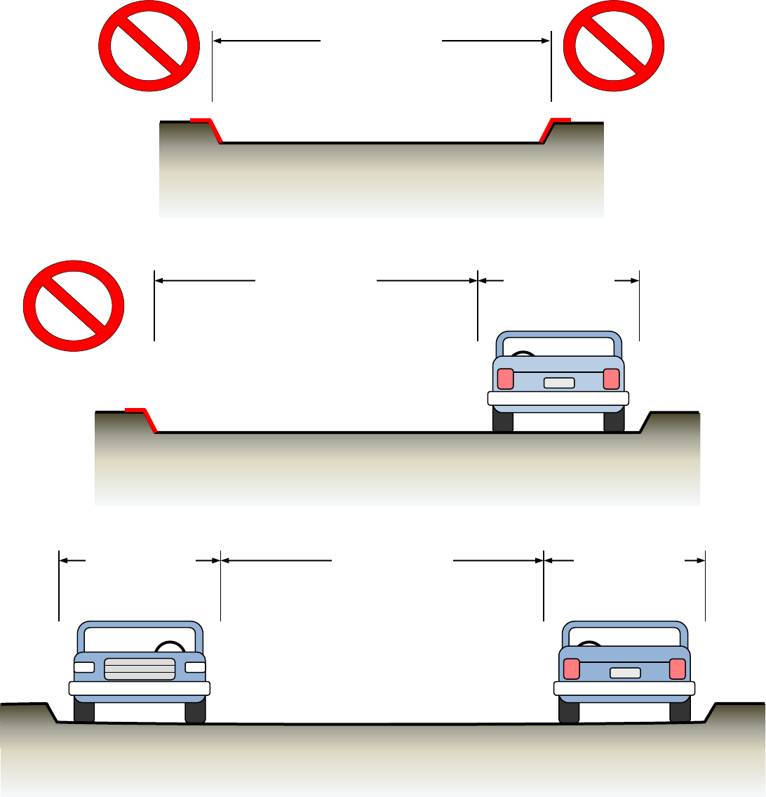
Fire Master Plans for Commercial & Residential Development: B-09 February 23, 2021
37
Minimum Road Widths
Measured from top face of curb to top face of curb for standard vertical curbs or flow
line to flow line for rolled, ramped, or other curb types.
FIRE LANE
20’ minimum
P
P
ROADWAY LESS THAN 28’
Parking prohibited.
Roadway is required to be posted as a fire lane.
FIRE LANE
20’ minimum
PARKING
8’ minimum
PARKING
8’ minimum
ROADWAY 36’ OR WIDER
Parking permitted on both sides
FIRE LANE
20’ minimum
P
PARKING
8’ minimum
ROADWAY AT LEAST 28’ BUT LESS THAN 36’
Parking permitted on one side only.
Roadway is required to be posted as a fire lane.
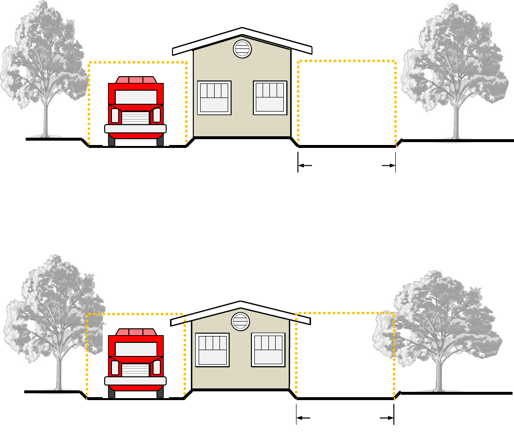
Fire Master Plans for Commercial & Residential Development: B-09 February 23, 2021
38
ATTACHMENT 4
Fire Apparatus Access Roadway Clearance
For Typical Gated Community Guard House
Fire lane width reductions detailed below are applicable only to the area immediately adjacent to
the guard house or gate. Roads leading up to and beyond the guard house or gate shall meet
standard fire lane width requirements prescribed in Section 2.A.5 of this guideline.
PROPER CLEARANCE PROVIDED
Eaves and vegetation do not encroach upon the 13’-wide by 13’-6”
high minimum dimensions allowed for the fire access roadway next
to the guard house.
13’ min. width
for gated entries
INSUFFICIENT CLEARANCE
While a 13’-wide access roadway is provided next to the guard
house, eaves and vegetation encroach upon the minimum clear
height of the fire lane.
13’ min. width
for gated entries
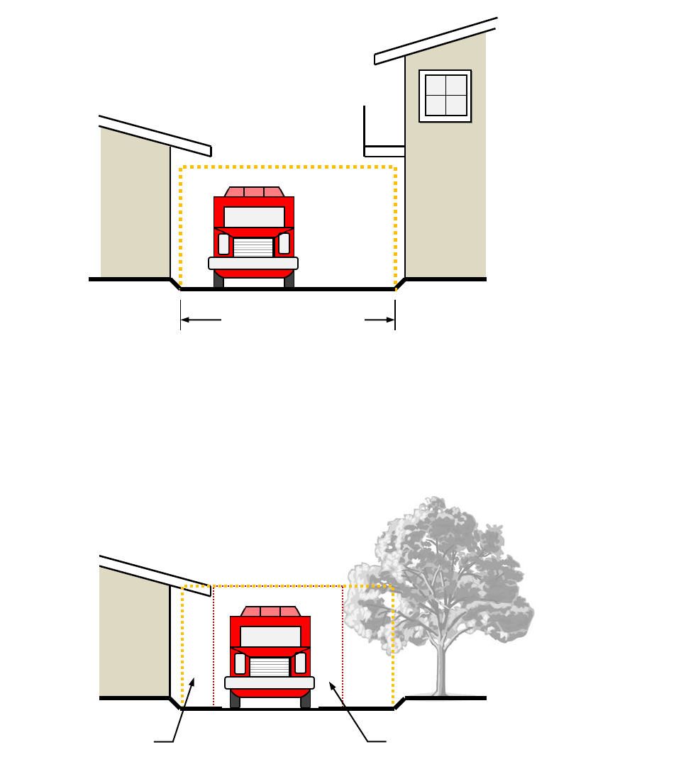
Fire Master Plans for Commercial & Residential Development: B-09 February 23, 2021
39
ATTACHMENT 5
Fire Apparatus Access
Roadway Clearance
INSUFFICIENT CLEARANCE
A 20’-wide roadway has been provided, but eaves and vegetation
effectively reduce the clear dimensions below required minimums.
Clearance provided
Clearance required
20’ minimum width
13’-6” minimum height
PROPER CLEARANCE PROVIDED
Eaves, balconies, and other obstructions do not encroach upon the
20’ wide by 13’-6” high fire access roadway envelope. As projections
over the fire lane can interfere with firefighting and rescue
operations, such obstructions shall be limited.
Fire Master Plans for Commercial & Residential Development: B-09 February 23, 2021
40
ATTACHMENT 6
“S” Curves
NOT PERMITTED
OCFA apparatus are unable to
negotiate tight “S” curves, such
as the one shown to the left.
PERMITTED
A 60’ straight leg is required
between the turns in a compound
curve to provide sufficient recovery
distance for the apparatus.
Alternatively, the length of the
straight leg may be reduced if the
road width and/or turning radii are
increased to allow for a wider turn.
Provide a swept-path analysis; see
Attachment 30 for inputs.
NOTE: Parking is not permitted in
any of these configurations at the
dimensions shown.
20’
20’
40’
60’
Drawings not to scale; for illustration purposes only.
20’
20’
40’
Fire Master Plans for Commercial & Residential Development: B-09 February 23, 2021
41
ATTACHMENT 7
Minimum Turnaround and Hammerhead Dimensions
NOTE: Parking is not permitted in these turnarounds at the dimensions shown.
Standard
turnaround
20’
Offset
turnaround
20’
40’
varies (42’ minimum)
40’
varies (28’ min.)
Fire Master Plans for Commercial & Residential Development: B-09 February 23, 2021
42
NOTE: Parking is not permitted in any of these hammerheads at the dimensions shown.
* Wherever possible, increase this dimension by five feet.
25’
20’*
45’*
29’*
20’
40’*
25’*
12’*
25’*
33’*
20’
26’
70’
20’
21’*
50’*
20’
50’*
20’
20’
25’*
Fire Master Plans for Commercial & Residential Development: B-09 February 23, 2021
43
ATTACHMENT 8
Fire Lane Parking Violations
The California Fire Code (CFC) and California Vehicle Code (CVC) specify rules of the
road for stopping, standing, and parking in fire lanes or near fire hydrants.
A. Section 22500.1 states that no person shall stop, park, or leave standing any
vehicle whether attended or unattended, in any location designated as a fire lane by
the Fire Authority except when necessary to avoid conflict with other traffic or in
compliance with the direction of a peace officer or official traffic control device.
Vehicles illegally parked in a fire lane may be towed per CVC 22953(b).
B. There shall be no parking of any vehicles other than fire department vehicles within
15 feet of either side of a fire hydrant in accordance with CVC 22514(c). Such
vehicles may be towed per CVC 22651(e).
C. CVC 22658(a) permits the owner or person in lawful possession of any private
property, subsequent to notifying local law enforcement, to cause the removal of a
vehicle parked on such property to the nearest public garage, if:
1) A sign is displayed in plain view at all entrances to the property specifying:
a) The ordinance prohibiting public parking, and
b) A notation indicating that vehicles will be removed at the owner’s expense,
and
c) The telephone number of the local traffic law enforcement agency, or
2) The lot or parcel upon which the vehicle is parked has a single-family dwelling.
D. CFC 503.4 states that the required width of a fire apparatus access road shall not
be obstructed in any manner, including parking of vehicles. Minimum required
widths and clearances shall be maintained at all times.
E. CFC 507.5.4 states that vehicles and other obstructions shall not be placed or kept
near fire hydrants, fire department inlet connections or fire-protection system control
valves in a manner that would prevent such equipment or fire hydrants from being
immediately discernible. The fire department shall not be deterred or hindered from
gaining immediate access to fire-protection equipment or hydrants.
Fire Master Plans for Commercial & Residential Development: B-09 February 23, 2021
44
ATTACHMENT 9
Fire Lane Identification – Red Curbs
1. Fire lane entrance sign(s) shall also be provided per Attachment 10 or 11.
2. Curbs shall be painted OSHA safety red.
3. “FIRE LANE – NO PARKING” shall be painted on top of curb in 3” white lettering
at a spacing of 30’ on center or portion thereof.
STANDARD CURB
ROLLED CURB
8”
NO CURB/
FLARED CURB
8”
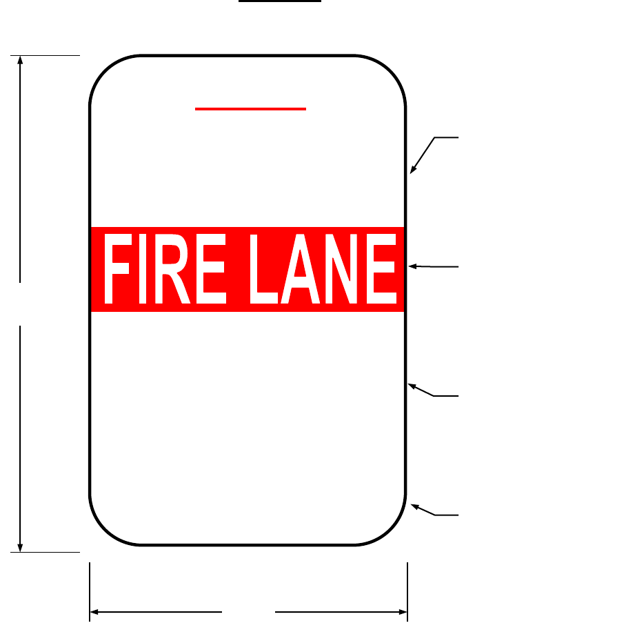
Fire Master Plans for Commercial & Residential Development: B-09 February 23, 2021
45
ATTACHMENT 10
Specifications for
Fire Lane Entrance Signs
To be used only at vehicle entry points
to areas that contain “Fire Lane—No Parking” signs or red curbs
All sign and lettering dimensions shown are minimums. “Arial Narrow” font is used in sample
above though other legible sans-serif fonts may be acceptable.
This sign shall be posted at all vehicle entrances to areas marked with either red curbs or fire
lane “No Parking” signs. Signs shall be securely mounted facing the direction of travel and
clearly visible to oncoming traffic entering the designated area. Signs shall be made of durable
material and installed per Attachments 13 and 14.
Towing company contact information is required for all properties with a standing written
agreement for services with a towing company per the California Vehicle Code.
1-3/8” bold red
lettering on white
reflective
background
30”
1-3/8” bold red
lettering on white
reflective
background
2-3/4” bold white
reflective lettering
on red
background
1” red lettering on
white reflective
background
18”
NOTICE
NO PARKING IN
AREAS MARKED AS
VIOLATING VEHICLES
WILL BE CITED
OR TOWED AT
OWNER’S EXPENSE
LAW AGENCY NAME & PHONE #
TOWING COMPANY NAME & PHONE #
CVC 22658(a) CVC 22500.1
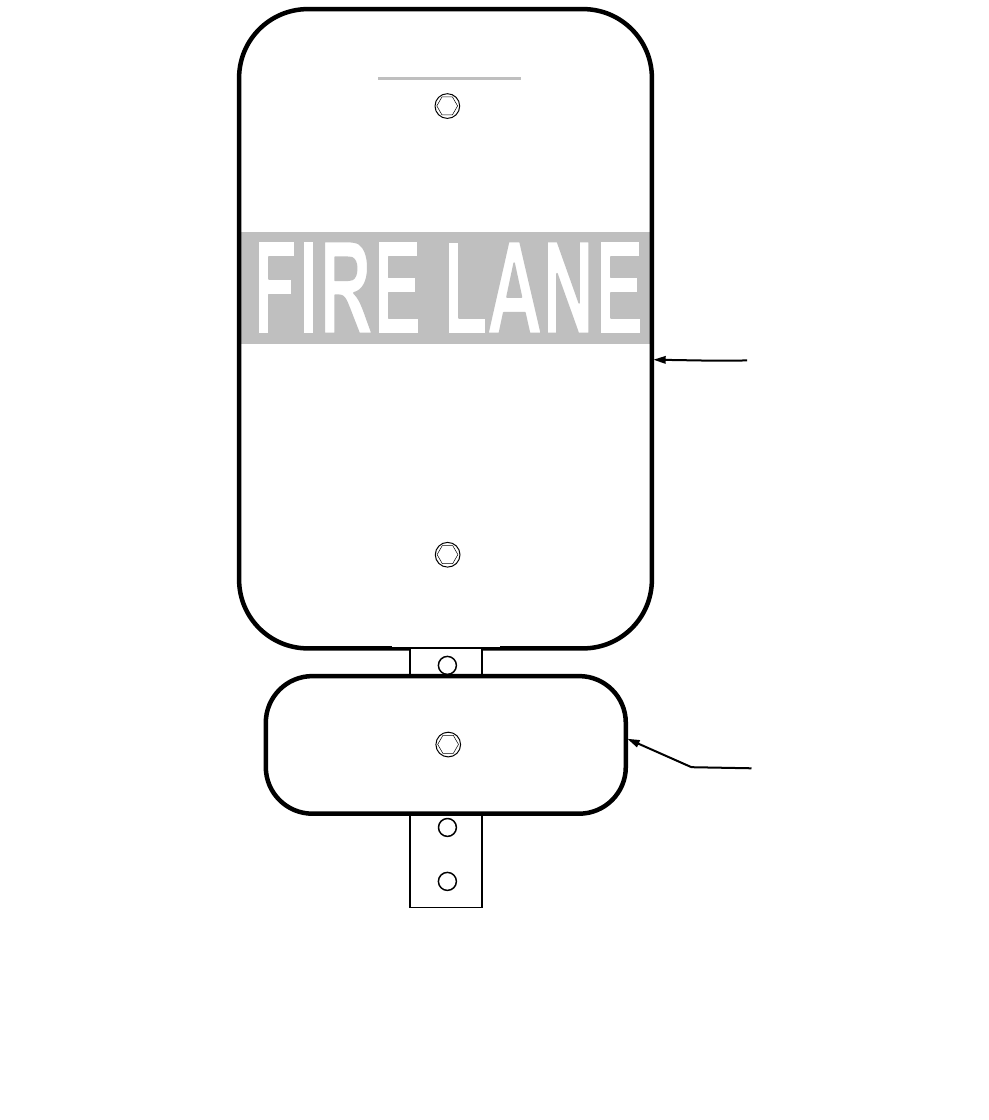
Fire Master Plans for Commercial & Residential Development: B-09 February 23, 2021
46
ATTACHMENT 11
Specifications for
Alternate Location of
Towing Company Information
NOTICE
NO PARKING IN
AREAS MARKED AS
VIOLATING VEHICLES
WILL BE CITED
OR TOWED AT
OWNER’S EXPENSE
LAW AGENCY NAME & PHONE #
CVC 22658(a) CVC 22500.1
Fire lane entrance
sign shall meet all
OCFA standards
detailed in this
guideline
Minimum 1” red
lettering on white
reflective
background
TOWING COMPANY NAME
TOWING COMPANY PHONE #
Towing company contact information is required for all properties with a standing written
agreement for services with a towing company per the California Vehicle Code.
To facilitate periodic changes in towing company contracts, the towing company contact
information may be posted on a separate sign mounted directly below the fire lane
entrance sign instead of on the entrance sign itself. The method of attachment to the
post shall not obscure the wording on either sign.
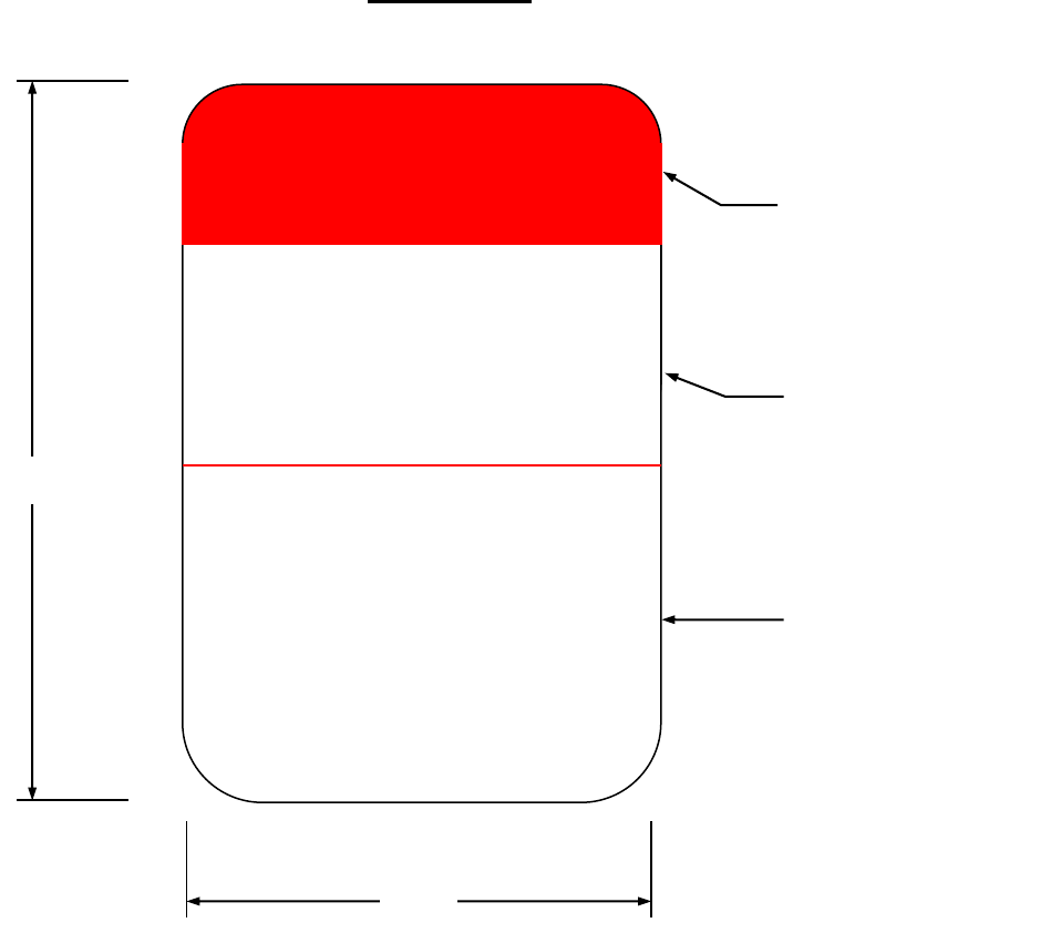
Fire Master Plans for Commercial & Residential Development: B-09 February 23, 2021
47
ATTACHMENT 12
Specifications for
Fire Lane No Parking Signs
FIRE LANE
NO
PARKING
VIOLATING VEHICLES
WILL BE CITED
OR TOWED AT
OWNER’S EXPENSE
CVC 22500.1
CVC 22658(a)
2” bold, condensed
white reflective
lettering on red
background
2” bold, condensed
red lettering on
white reflective
background
1” red lettering on
white reflective
background
12”
18”
All sign and lettering dimensions shown are minimums. “Arial Narrow” font is used in
sample above though other legible sans-serif fonts may be acceptable.
In areas where fire lane parking restrictions are enforced by the California Highway
Patrol, “NO STOPPING—FIRE LANE” signs meeting Caltrans standards shall be
used.
Signs shall be securely mounted facing the direction of travel and clearly visible to
oncoming traffic entering the designated area. Signs shall be made of durable
material and installed per Attachments 13 and 14.
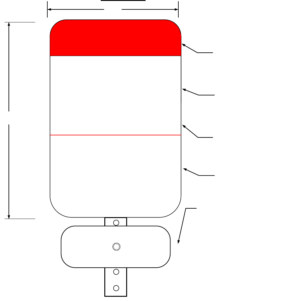
Fire Master Plans for Commercial & Residential Development: B-09 February 23, 2021
48
ATTACHMENT 12a
Specifications for Cul-de-Sac
Fire Lane No Parking Signs
FIRE LANE
NO
PARKING
IN CUL-DE-SAC
VIOLATING VEHICLES
WILL BE CITED
OR TOWED AT
OWNER’S EXPENSE
CVC 22500.1, 22658(a)
2” bold, condensed
white reflective
lettering on red
background
2” bold, condensed
red lettering on
white reflective
background
1” red lettering on
white reflective
background
18”
All sign and lettering dimensions shown are minimums. “Arial Narrow” font is used in
sample above though other legible sans-serif fonts may be acceptable.
Signs shall be securely mounted facing the direction of travel and clearly visible to
oncoming traffic entering the designated area. Signs shall be made of durable
material and installed per Attachments 13 and 14.
1-3/8” bold,
condensed red
lettering on white
reflective background
Minimum 2” red lettering
on white reflective
background; provide
“BEGIN” sign at entry into
cul-de-sac and “END” sign
when leaving cul-de-sac.
“BEGIN” or “END” sign
may be omitted where cul-
de-sac is the continuation
of a no parking zone on
streets <36’ wide.
BEGIN
12”

Fire Master Plans for Commercial & Residential Development: B-09 February 23, 2021
49
ATTACHMENT 12b
Specifications for Alternative
Fire Lane No Parking Signs
FIRE LANE
NO
PARKING
BEYOND THIS POINT
EXCEPT IN
DESIGNATED STALLS
VIOLATING VEHICLES
WILL BE CITED
OR TOWED AT
OWNER’S EXPENSE
CVC 22500.1, 22658(a)
All sign and lettering dimensions shown are minimums. “Arial Narrow” font used is
used in sample above though other legible sans-serif fonts may be acceptable.
Signs shall be securely mounted facing the direction of travel and clearly visible to
oncoming traffic entering the designated area. Signs shall be made of durable
material and installed per Attachments 13 and 14.
Additional verbiage
shall be 1” bold,
condensed red
lettering on white
reflective background.
Where parking stalls
are not present, sign
may omit “except in
designated stalls“ and
sign height may be
reduced to 18”.
Specifications for the
rest of the sign shall
match those of
standard fire lane no
parking signs.
12”
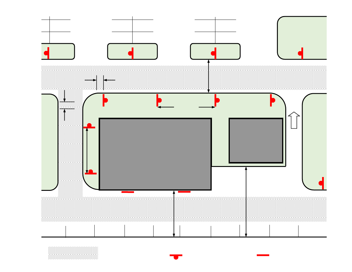
Fire Master Plans for Commercial & Residential Development: B-09 February 23, 2021
50
ATTACHMENT 13
Fire Lane No Parking Sign Locations
50’ max.
20’ Fire Lane
Fire Lane Sign
(post mounted)
Fire Lane Sign
(wall mounted)
Signs are required within 3’ of the end of the curb return at the beginning of each “block”
along the fire lane and spaced a maximum of 50’ along the entire designated lane. A sign
shall be located within a reasonable distance of the end of each block as necessary to clearly
identify the extent of the no parking zone. One sign is required for each island adjacent to the
fire lane that is large enough to accommodate a parked car.
Signs shall be securely mounted facing the direction of travel and clearly visible to oncoming
traffic entering the designated area. Signs shall be made of durable material and installed per
Attachment 14. Where sign posts are not practical, signs may be mounted on a wall or fence
and are allowed to be oriented perpendicular to the length of the fire lane. OCFA inspectors
will determine if additional signs or sign locations are required.
3’ max. from
end of curb
return
D
O
N
O
T
E
N
T
E
R
50’
max.
Where the width of the drive aisle is
between 28’ and 36’ parking is allowed on
one side; signs are required on the other
Where the drive aisle is
at least 36’ wide, signs
are not required
Where the drive aisle is
less than 28’ wide, signs
are required on both sides
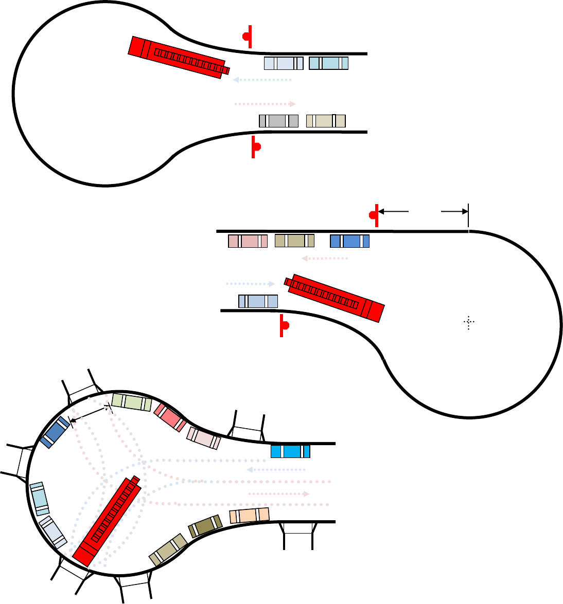
Fire Master Plans for Commercial & Residential Development: B-09 February 23, 2021
51
ATTACHMENT 13a
Fire Lane No Parking Sign Locations for Cul-de-sacs
Where size and placement of
driveways ensure sufficient space is
available to execute a three-point
turn, no-parking signs are
unnecessary.
20’
min.
Offset 40’ radius cul-de-sac: “no-parking
entire cul-de-sac begin” and “end” signs
shall be located at the point where the street
begins to widen into the bulb and at a point
40’ from where the cul-de-sac and street are
tangent (see Attachment 12a)
40’
Drawing
not to scale
Standard 40’ radius cul-de-sac
“no-parking entire cul-de-sac begin”
and “end” signs shall be located at the
point where the street begins to widen
into the bulb (see Attachment 12a)
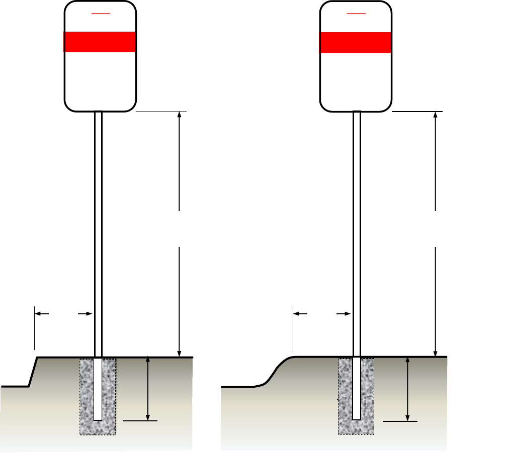
Fire Master Plans for Commercial & Residential Development: B-09 February 23, 2021
52
ATTACHMENT 14
Mounting Specifications for
Fire Lane Entrance and No Parking Signs
Signs shall be mounted facing the direction of vehicular travel.
Signs may be mounted on existing posts or buildings where the centerline of the sign is
no more than 24” from the edge of the roadway.
Depth of bury shall be a minimum of 24” and rebar, a concrete footing, or another
method to prevent removal of the sign is recommended. Footings for signs located in
the public right-of-way shall be per the local jurisdiction’s requirements.
24”
24”
Pedestrian areas: 7’
All other areas: 5’
ROLLED CURB
STANDARD CURB
Pedestrian areas: 7’
All other areas: 5’
18”
24”
Concrete footing or
other approved means
of stabilization
NOTICE
NO PARKING IN
AREAS MARKED AS
VIOLATING VEHICLES
WILL BE CITED
OR TOWED AT
OWNER’S EXPENSE
LAW AGENCY NAME & PHONE
#
TOWING COMPANY NAME &
PHONE #
CVC 22658(a) CVC 22500.1
FIRE LANE
NOTICE
NO PARKING IN
AREAS MARKED AS
VIOLATING VEHICLES
WILL BE CITED
OR TOWED AT
OWNER’S EXPENSE
LAW AGENCY NAME & PHONE
#
TOWING COMPANY NAME &
PHONE #
CVC 22658(a) CVC 22500.1
FIRE LANE
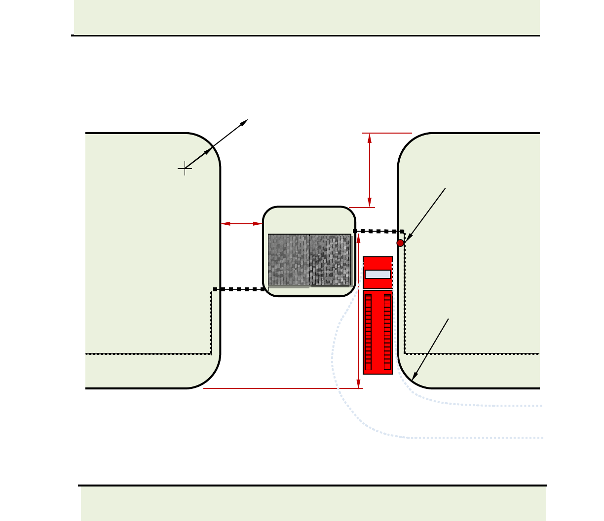
Fire Master Plans for Commercial & Residential Development: B-09 February 23, 2021
53
ATTACHMENT 15
Minimum Gate Setbacks
13’
min.
30’ min.
46’/60’ min.
gate setback
Key switch on
right side of gate
(place on left
side in Irvine)
Turning Radii (typical):
20’ inside
40’ outside
Drawing
not to scale
Increased radii
may be required at
corners to facilitate
maneuvering fire
apparatus into the
13’ wide roadway
depending on how
close the
guardhouse island
is to the street.
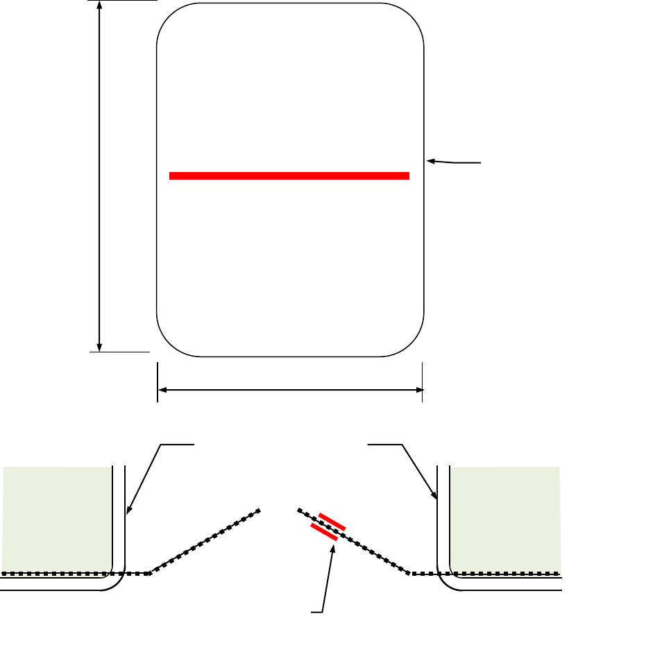
Fire Master Plans for Commercial & Residential Development: B-09 February 23, 2021
54
ATTACHMENT 16
Specifications for
“Fire Lane - No Parking” Signs for
Manually Operated Gates and Barriers
12”
18”
Curb(s) shall be marked
as fire lane if road < 36’
wide.
NO
PARKING
All sign and lettering dimensions shown are minimums. “Arial Narrow” font used is used in
sample above though other legible sans-serif fonts may be acceptable.
“Fire Lane—No Parking” sign shown in Attachment 12 may be used as an alternative. Signs
shall be securely mounted on the front and back face of the gate clearly visible to traffic
entering the designated area. Signs shall be made of a durable material.
2” bold, condensed
red lettering on white
reflective background
FIRE
LANE
Mount one sign on
each face of gate.
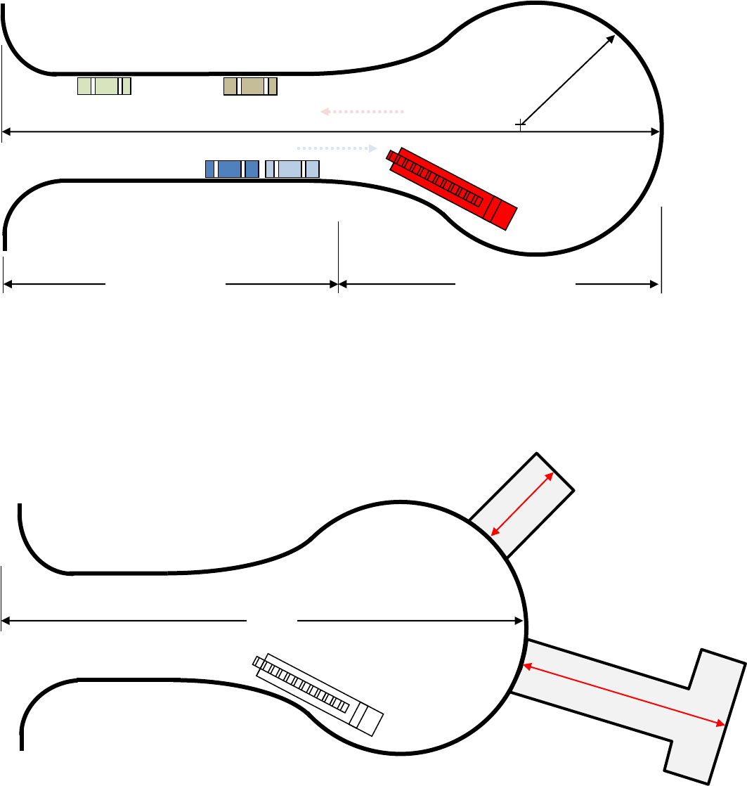
Fire Master Plans for Commercial & Residential Development: B-09 February 23, 2021
55
ATTACHMENT 17
Cul-de-sacs and Dead-end Roadways
No more than 150’: no
turnaround required in spur
Radius: 40’ min.
Drawing
not to scale
>150’
More than 150’: turnaround
required in spur
1) Cul-de-sac streets greater than 150 feet in length that are required fire lanes shall be provided with
a 40-foot minimum turning radius in the bulb.
Cul-de-sac “neck”
Cul-de-sac “bulb”
2) Where a spur road or private driveway that is a required fire lane is accessed via the cul-de-sac road,
the driveway or spur shall be no more than 150’ in length unless an approved turnaround has been
provided within 150’ of the end of the spur or driveway.
>150’
Radius:
40’ min.
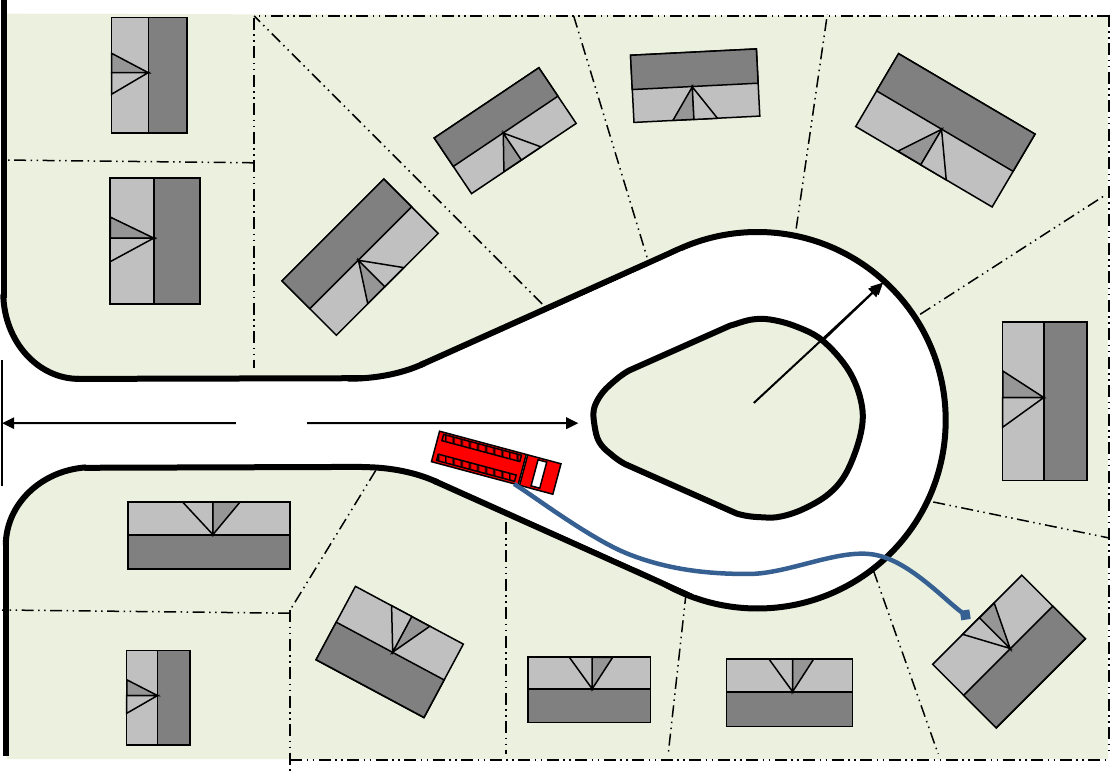
Fire Master Plans for Commercial & Residential Development: B-09 February 23, 2021
56
ATTACHMENT 18
Cul-de-sacs Longer than 150’ with Islands
*
Attic protection required where hose-pull distance from the portion of the cul-de-sac preceding the island
to the front entry of a sprinklered home exceeds 300’. For existing unsprinklered homes, hose pull may
not exceed 150’ to the most remote point around the perimeter of the home or sprinklers with attic
protection will be required.
Cul-de-sac streets greater than 150 feet in length may contain a center island provided that:
1) A minimum 28-foot-wide drive lane with an adequate inside turning radius is provided, and
2) The island is designated a no parking area with red curbs or signs, and
3) Island landscaping will not intrude into the drive lane, and
4) An NFPA 13-D sprinkler system with full protection of the attic space(s) is installed in the homes where
hose-pull requirements can only be satisfied by taking access from the drive lane beyond the beginning of the
island.
*
*
*
>150’
Drawing
not to scale
min. outer radius:
40’ (no parking)
48’ (parking)
Hose-pull >300’ for a sprinklered
home
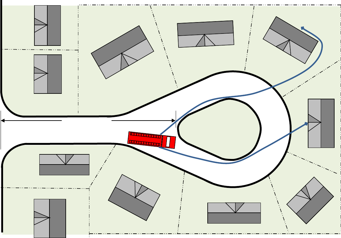
Fire Master Plans for Commercial & Residential Development: B-09 February 23, 2021
57
Access to the homes will be measured along an approved route around the island and any other obstructions in
the path of travel from the point where the island begins to impede fire apparatus. If hose-pull to the main entry
of a sprinklered home exceeds 300’ (or 150’ to the most remote point around the perimeter for unsprinklered
homes), the portion of the bulb beyond the island shall be designed as a fire lane or other mitigating features
shall be provided. If all homes are in access from the area preceding the island, the portion of the bulb beyond
the island is not required to comply with OCFA fire access roadway requirements. The neck and portion of the
bulb preceding the island shall meet all other fire lane requirements prescribed in this guideline if it is a required
fire lane.
Up to 150’
maximum
Drawing
not to scale
ATTACHMENT 19
Cul-de-sacs up to 150’ with Islands
Hose-pull up to 300’
max. to main entry
for sprinklered
home
Hose-pull 150’ max. to
most remote point of
unsprinklered home
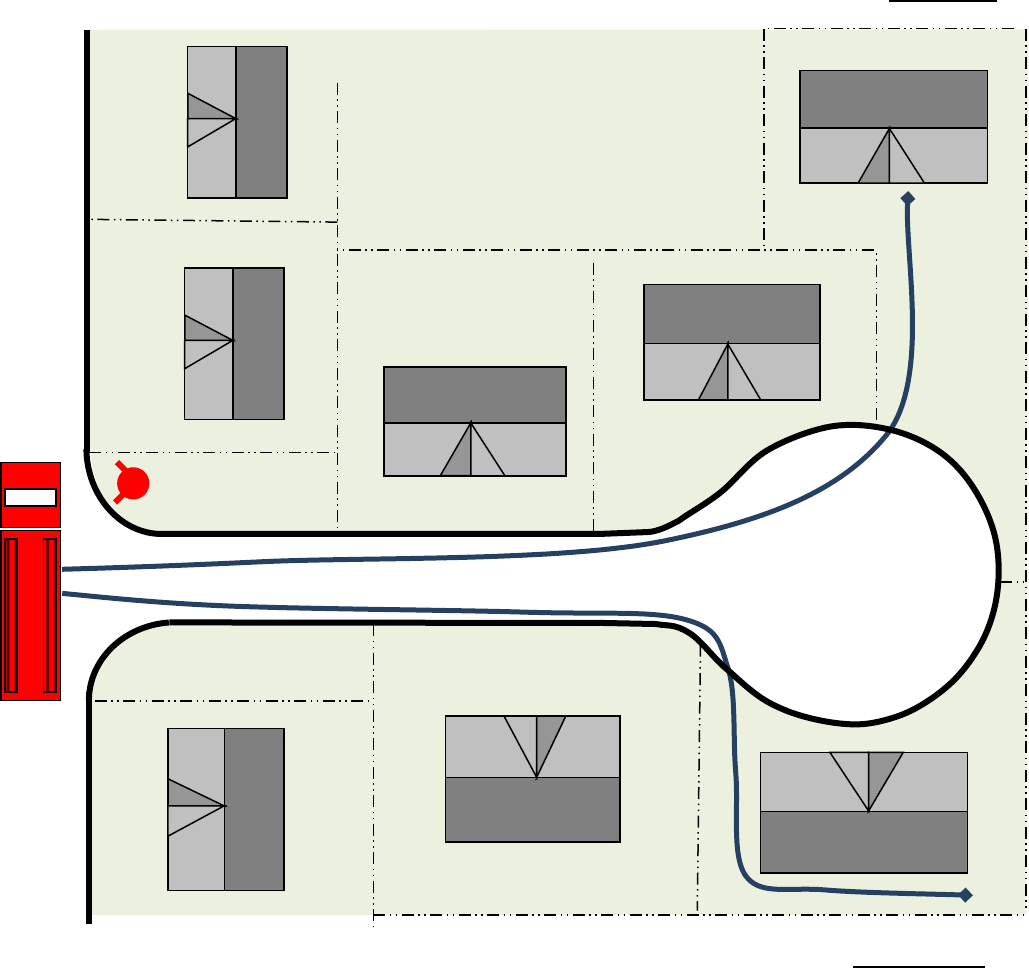
Fire Master Plans for Commercial & Residential Development: B-09 February 23, 2021
58
ATTACHMENT 20
Short Cul-de-sacs and Dead-end Roads
If hose-pull distance can be satisfied without fire apparatus entering the cul-de-sac or dead-end road, and the
road is not otherwise required to be a fire lane as determined by the fire code official, the street is not required
to have a bulb or hammerhead with minimum OCFA turning radii or meet other standard fire lane
requirements.
Drawing
not to scale
NOT A REQUIRED FIRE LANE
Hose-pull up to 300’ max. to
main entry for sprinklered
homes
Hose-pull 150’ max. to most
remote point of unsprinklered
homes
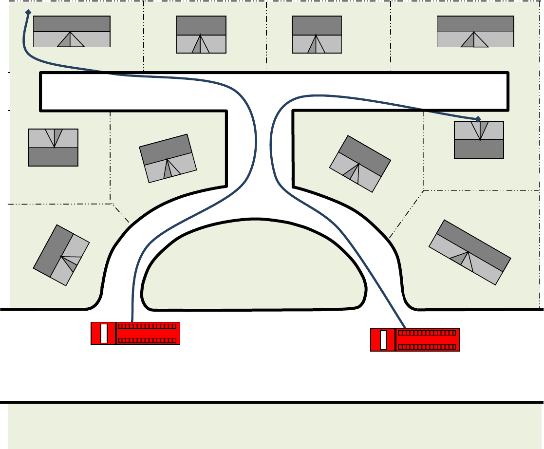
Fire Master Plans for Commercial & Residential Development: B-09 February 23, 2021
59
ATTACHMENT 21
Eyebrows
If the eyebrow does not meet OCFA’s minimum turning radius and width requirements, fire
department access will be measured from the nearest available fire lane around the island and
any other obstructions. If hose-pull to the main entry of a sprinklered home exceeds 300’ (or
150’ to the most remote point around the perimeter for unsprinklered homes), the eyebrow shall
be designed as a fire lane or other mitigating features shall be provided.
Drawing
not to scale
Hose-pull up to 300’ max. to
main entry of sprinklered
home
Hose-pull 150’ max. to most remote
point of unsprinklered home
Fire Master Plans for Commercial & Residential Development: B-09 February 23, 2021
60
ATTACHMENT 22
Sample Parking Enforcement Letter
Date
Planning and Development Services Section
Orange County Fire Authority
1 Fire Authority Road
Irvine, CA. 92602
Re: (Project Name, Location, and Service Request Number)
Parking Enforcement Plan
The fire lane parking enforcement plan for the above referenced project is stated as
follows:
All fire lanes within (list development address or tract information) shall be maintained
and in no event shall parking be permitted along any portion of a street or drive that
required fire lanes or any area designated as a fire lane for turn-around purposes either
during construction or after occupancy.
(Association name) shall adopt reasonable rules and regulations regarding the parking
of vehicles along the streets, roads and or drives within the project that are not in
conflict with applicable law.
In furtherance thereof, (Association name), through its officers, committees and agents,
will establish the “parking” and “no parking” areas within the property in accordance with
Section 22658 of the California Vehicle Code and OCFA Guideline B-09. The law shall
be enforced through such rules and regulations by all lawful means, including, written
warnings, citing, levying fines and towing vehicles in violation.
(Association name) will contract with a certified patrol and towing company to remove
vehicles that violate no parking restrictions. First time violators will receive a written
warning and with subsequent violations, the vehicle shall be subject to towing. The
vehicle owner shall be responsible for all costs incurred in remedying such violation,
including without limitation towing cost, citations and legal fees.
Company Name
Authorized Agent Signature
Cc:

Fire Master Plans for Commercial & Residential Development: B-09 February 23, 2021
61
ATTACHMENT 23
CFC TABLE B105.1(2):
Minimum Required Fire Flow and Flow Duration
for Buildings in OCFA Jurisdiction
S: Provided with an approved sprinkler system throughout the structure NS: No fire sprinklers or partially protected with a sprinkler system
FIRE FLOW CALCULATION AREA
(square feet)
DETACHED SINGLE-FAMILY
RESIDENCE/DUPLEX
OTHER BUILDINGS
FIRE FLOW
(gallons per minute
at 20 psi residual)
DURATION
(hours)
FIRE FLOW (gallons
per minute at 20 psi
residual)
DURATION
(hours)
Type IA/IB
Type IIA/IIIA
Type IV/VA
Type IIB/IIIB
Type VB
NS
S
NS
S
0-22700
0-12700
0-8200
0-5900
0-3600
1000
1000
1
1500
1500
2
22701-30200
12701-17000
8201-10900
5901-7900
3601-4800
1750
1000
NS: 2
S: 1
1750
1500
30201-38700
17001-21800
10901-12900
7901-9800
4801-6200
2000
1000
2000
1500
38701-48300
21801-24200
12901-17400
9801-12600
6201-7700
2250
1125
2250
1500
48301-59000
24201-33200
17401-21300
12601-15400
7701-9400
2500
1250
2500
1500
59001-70900
33201-39700
21301-25500
15401-18400
9401-11300
2750
1375
2750
1500
70901-83700
39701-47100
25501-30100
18401-21800
11301-13400
3000
1500
NS: 3
S: 1
3000
1500
3
83701-97700
47101-54900
30101-35200
21801-25900
13401-15600
3250
1625
3250
1625
97701-112700
54901-63400
35201-40600
25901-29300
15601-18000
3500
1750
3500
1750
112701-
128700
63401-72400
40601-46400
29301-33500
18001-20600
3750
1875
3750
1875
128701-
145900
72401-82100
46401-52500
33501-37900
20601-23300
4000
2000
NS: 4
S: 1
4000
2000
4
145901-
164200
82101-92400
52501-59100
37901-42700
23301-26300
4250
2125
4250
2125
164201-
183400
92401-103100
59101-66000
42701-47700
26301-29300
4500
2250
4500
2250
183401-
203700
103101-
114600
66001-73300
47701-53000
29301-32600
4750
2375
4750
2375
203701-
225200
114601-
126700
73301-81100
53001-58600
32601-36000
5000
2500
5000
2500
225201-
247700
126701-
139400
81101-89200
58601-65400
36001-39600
5250
2625
5250
2625
247701-
271200
139401-
152600
89201-97700
65401-70600
39601-43400
5500
2750
5500
2750
271201-
295900
152601-
166500
97701-106500
70601-77000
43401-47400
5750
2875
5750
2875
295901+
166501+
106501-115800
77001-83700
47401-51500
6000
3000
6000
3000
115801-125500
83701-90600
51501-55700
6250
3125
6250
3125
125501-135500
90601-97900
55701-60200
6500
3250
6500
3250
135501-145800
97901-106800
60201-64800
6750
3375
6750
3375
145801-156700
106801-113200
64801-69600
7000
3500
7000
3500
156701-167900
113201-121300
69601-74600
7250
3625
7250
3625
167901-179400
121301-129600
74601-79800
7500
3750
7500
3750
179401-191400
129601-138300
79801-85100
7750
3875
7750
3875
191401+
138301+
85101+
8000
4000
8000
4000

Fire Master Plans for Commercial & Residential Development: B-09 February 23, 2021
62
ATTACHMENT 24
CFC TABLE C102.1:
Hydrant Quantity and Spacing in OCFA Jurisdiction
DETACHED SINGLE FAMILY RESIDENCES/DUPLEXES with SPRINKLERS
Flow
Requirement
from Table
B105.1(2)
Minimum
Number of
Hydrants
Maximum Distance
to a Hydrant
Maximum Distance
between Hydrants
1
Average Distance
between Hydrants
1
Thru road
Dead-end
Thru road
Dead-end
Thru road
Dead-end
1000 - 1750
1
300
250
600
500
600
500
1751+
Use the table below
ALL OTHER STRUCTURES
Flow
Requirement
from Table
B105.1(2)
Minimum
Number of
Hydrants
Maximum Distance
to a Hydrant
Maximum Distance
between Hydrants
1,2
Average Distance
between Hydrants
1,2
Thru road
Dead-end
Thru road
Dead-end
Thru road
Dead-end
1000 - 1750
1
250
200
500
400
500
400
1751 - 2250
2
225
175
450
350
450
350
2251 - 2500
3
225
175
450
350
450
350
2501 - 3000
3
225
175
450
350
400
300
3001 - 4000
4
210
160
420
320
350
250
4001 - 5000
5
180
130
360
260
300
200
5001 - 5500
6
180
130
360
260
300
200
5501 - 6000
6
150
100
300
200
250
150
6001 - 7000
7
150
100
300
200
250
150
7001+
1 per 1000 gpm
or fraction thereof
120
70
240
140
200
100
All distances are in feet.
1
Where streets are provided with median dividers which cannot be crossed by fire fighters pulling hose lines, or where arterial streets are
provided with four or more traffic lanes and have a traffic count of more than 30,000 vehicles per day, hydrant spacing shall average 500 feet on
each side of the street and be arranged on an alternating basis.
2
Where new water mains are extended along streets where hydrants are not needed for protection of structures or similar fire problems, fire
hydrants shall be provided at spacing not to exceed 1,000 feet to provide for transportation hazards.
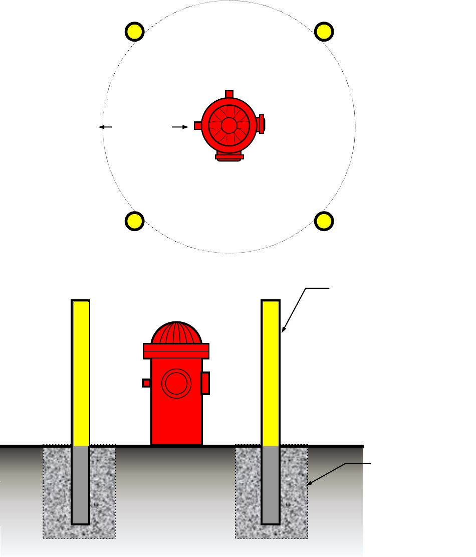
Fire Master Plans for Commercial & Residential Development: B-09 February 23, 2021
63
ATTACHMENT 25
Protection of Hydrants, Detector Checks,
Fire Department Connections, and other Appurtenances
3’
minimum
4” diameter
concrete-filled pipe
embedded in
concrete; top of
bollard a minimum
3’ above grade
15” diameter
footing; bollard
shall be
embedded a
minimum 3’ in
footing
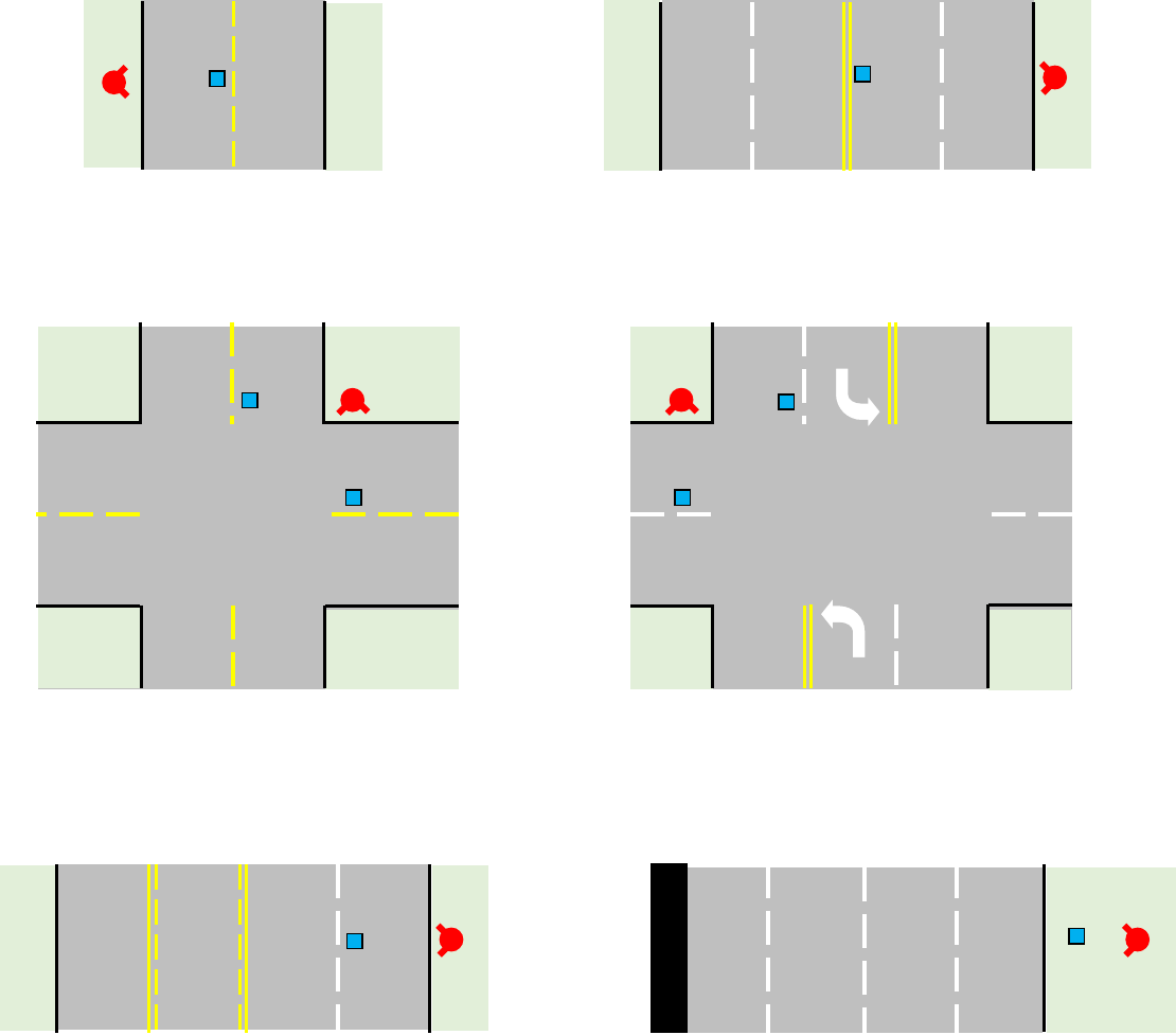
Fire Master Plans for Commercial & Residential Development: B-09 February 23, 2021
64
ATTACHMENT 26
“Blue Dot” Reflective Hydrant Marker Location
The developer may contact the local water company to arrange the installation of the
blue dots. If the water agency does not participate in the blue dot program, the
developer is still responsible to install the dots in an approved manner.
TWO LANE STREET
MULTI-LANE STREET
INTERSECTION
INTERSECTION WITH TURN LANES
MULTILANE STREET WITH TURN LANE
FREEWAYS AND EXPRESSWAYS
Fire Master Plans for Commercial & Residential Development: B-09 February 23, 2021
65
ATTACHMENT 27
Hose Pull
In the example above, assume that the parking lot is not accessible to fire apparatus
due to turning radii and fire lane widths less than the required minimums.
All portions of building “A” are within 150’ feet of the public road as measured
along the path of firefighter travel. This building is in access.
Building “B” is also in access despite the obstruction presented by the planter
and hedges due to its proximity to the road.
Building “C” is out of access; the presence of a chainlink fence forces firefighters
to backtrack once they pass through the gate, increasing their travel distance to
the dashed part of the perimeter beyond 150’. On-site fire access roadways or a
change in the location of the gate and would be necessary to provide access to
Building “C”.
150’
Hose
Pull
A
B
C
Begin measurement
10’ from curb

Fire Master Plans for Commercial & Residential Development: B-09 February 23, 2021
66
ATTACHMENT 28
Requirements for Key boxes/Key switches by Jurisdiction
This table is provided for purposes of facilitating sharing of key boxes/key switches for emergency access
and security purposes by fire and police departments. It is not intended to be comprehensive or in any
way supersede the requirements of the local jurisdiction; please refer to the local municipal or security
code to verify the exact location of where devices are required for police access and other installation
specifications. For fire department Knox device requirements, please see Sections 5.E through 5.G of this
guideline for vehicle gates crossing fire lanes and Section 9.C.3 for pedestrian gates and buildings.
OCFA
1
IRVINE
1,2
OTHER
JURISDICTIONS
1
Vehicular
Parking Structures
See Section 9.C.3
of this guideline
Irvine Uniform
Security Code
Section 5-9-519
See local municipal
or security code
Vehicle Gates
See Section
5.E through 5.G
of this guideline
Irvine Uniform
Security Code
Section 5-9-519
Other
n/a
Resi
dential
Residential recreation areas
>5 units
See Section 9.C.3
of this guideline
Irvine Uniform
Security Code
Section 5-9-519
See local municipal
or security code
Common interior/exterior
circulation walkways and
hallways >3 units
Irvine Uniform
Security Code
Section 5-9-519
Other
n/a
Commercial/Industrial
Main entry of enclosed retail
shopping centers
See Section 9.C.3
of this guideline
Irvine Uniform
Security Code
Section 5-9-519
See local municipal
or security code
Main entry of multi-tenant
commercial/industrial
structures
Irvine Uniform
Security Code
Section 5-9-519
Pedestrian gates to common
exterior areas
Irvine Uniform
Security Code
Section 5-9-519
Other
n/a
1
Where additional devices beyond those required by the fire department are called for in the local
municipal or security code, they shall also be accessible for use by the fire department to facilitate
emergency response.
2
Knox boxes and key switches serving pedestrian gates and buildings shall be located four feet above
ground and within two feet of the strike side of the door. Refer to the Irvine Uniform Security Code,
Section 5-9-519 for specific requirements for devices serving electric vehicle and pedestrian gates.
Fire Master Plans for Commercial & Residential Development: B-09 February 23, 2021
67
ATTACHMENT 29
Distance from Hydrant to Engine, Engine to Building, Between
Hydrants
D
2
B
B
A
D
3
A: Hose Pull (Distance from Fire Engine to Building): Represents the amount of fire hose that firefighters must pull from the engine
to reach the structure. Hose pull may not exceed 150’ from the engine to the most remote point of the perimeter of the structure (for
sprinklered detached single family homes and duplexes 300’ to the front door). Hose pull is measured along the firefighter path of travel,
avoiding any obstacles, not “as the crow flies.” In the diagram below, firefighters would be able to reach the entire perimeter of the
building by pulling no more than 150’ of hose from one or more fire engines staged in the shaded portion of the fire lane; the engine in
the unshaded roadway has a hose pull distance greater than 150’ and the building would be considered “out of access” from that point.
For hydrant evaluation purposes, the shaded part of the fire lane is considered to serve the building and must meet hose lay
requirements. See Attachment 27 for further information on hose pull measurement and access to structures.
B: Hose Lay (Distance from Engine to a Hydrant): Represents the amount of hose that must be laid out of the engine to supply
water from the hydrant to the engine. No point along the portion of the fire lane serving the structure (the shaded road) may be farther
from a hydrant than the distance specified in CFC Table C102.1 (see Attachment 24). The hydrant may be located along portions of the
fire lane that exceed the hose pull distance (unshaded roadway) provided that it is 1) on the same property, 2) on an adjacent property
where an emergency access easement has been obtained, or 3) on a public road leading to the fire lane serving the property. Hose lay
is measured along the vehicle path of travel in the fire lane, not “as the crow flies.”
C: Hydrant Spacing (Distance between Hydrants)—the distance between hydrants serving the building shall not exceed that listed in
CFC Table C102.1, as measured along the fire lane. Hydrants located on portions of the fire lane that do not serve the building do not
need to be evaluated for spacing relative to each other, only with respect to hydrants that do serve the structure. For example, when
evaluating hydrant placement for the building shown in the diagram below, D
1
may exceed the hydrant spacing requirements, while D
2
and D
3
cannot. The “Average Spacing” from Table C102.1 shall be maintained to prevent multiple hydrants from being concentrated in
only one portion of the fire lane.
A
A
D
1
Max. 150’ hose pull
distance is exceeded
from this location
A
B
Fire Master Plans for Commercial & Residential Development: B-09 February 23, 2021
68
ATTACHMENT 30
Apparatus Data for Swept Path Analysis
Use the following inputs for analyzing the swept path of a “typical” OCFA fire truck. To
improve maneuverability for all OCFA apparatus, increase the speed of apparatus
navigation through tight turns, and reduce the potential for property damage and
resulting delays to emergency response, projections such as light poles, sign posts,
mailboxes, planter walls, and vegetation shall not be placed near the edge of the fire
lane where they can obstruct or be struck by portions of the vehicle that may overhang
the curb.
Width (cab) 8.00 feet
Width (mirror to mirror) 9.50 feet
Track (wheel) 8.50 feet
Lock to Lock Time 6 seconds
Steering Angle 40 degrees
Height Clearance 13.50 feet

Fire Master Plans for Commercial & Residential Development: B-09 February 23, 2021
69
ATTACHMENT 31
OCFA Notes for Electric Vehicle Gates
All of the notes listed below shall be placed on the plan verbatim, under the heading
“OCFA Notes for Electric Vehicle Gates.” Indicate the type of remote gate operator
under Note #1.
OCFA Notes for Electric Vehicle Gates
1) A remote opening device is required. The remote gate opening device that will be
installed is (check one):
3M Opticom
Click2Enter* (single-pulse mode with 1.5 second transmission window)
Fire Strobe Access Products, Inc.
Tomar
2) In the event of loss of normal power to the gate operating mechanism, it shall be
automatically transferred to a fail-safe mode allowing the gate to be pushed open by
a single firefighter without any other actions, knowledge, or manipulation of the
operating mechanism being necessary.
a) A battery may only be used in place of fail-safe manual operation when the gate
operator has a fail-open mode that will automatically, immediately, and
completely open the gate and keep it open upon reaching a low power threshold,
regardless of the presence of normal power.
b) Should the gate be too large or heavy for a single firefighter to open manually, a
secondary source of reliable power by means of an emergency generator or a
capacitor with enough reserve to automatically, immediately, and completely
open the gate upon loss of primary power shall be provided for fail-open
operation.
3) In addition to the remote operator, the gate control shall be operable by a Knox
emergency override key switch equipped with a dust cover. Upon activation of the
key switch, the gate shall open and remain open until returned to normal operation
by means of the key switch. Where a gate consists of two leaves, the key switch
shall open both simultaneously if operation of a single leaf on the ingress side does
not provide for the width, turning radii, or setbacks necessary for fire apparatus to
navigate the vehicle entry point.
4) The key switch shall be placed between 42” and 48” above the roadway surface at
the right side of the access gate within two feet of the edge of the roadway. In
Irvine, the switch shall be on the left side in accordance with Irvine’s Uniform
Security Ordinance.
5) The key switch shall be readily visible and unobstructed from the fire lane leading to
the gate.
6) The key switch shall be labeled with a permanent red sign with not less than ½”
contrasting letters reading “FIRE DEPT” or with a “Knox” decal.
