21
CHAPTER 3
Using Pure Data
SECTION 3.1
Basic objects and principles of operation
Now we are familiar with the basics of Pd let’s look at some essential objects
and rules for connecting them together. There are about 20 message objects
you should try to learn by heart because almost everything else is built from
them.
Hot and c old inlets
Most objects operating on messages have a “hot” inlet and (optionally) one or
more “cold” inlets. Messages received at the hot inlet, usually the leftmost one,
will cause c omputation to happen and output to be ge nerated. Messages on a
cold inlet will update the internal value of an object but not cause it to output
the result yet. This seems strange at first, like a bug. The reason is so that we
can order evaluation. This means waiting for sub-parts of a program to finish
in the right order before proceeding to the next step. From maths you know
that brackets describe the order of a calculation. The resultof4×10 −3isnot
the same as 4 ×(10 − 3), we need to calculate the parenthesised parts first. A
Pd program works the same way, you need to wait for the results from certain
parts before moving on.
10
33
* 5
+ 3
3
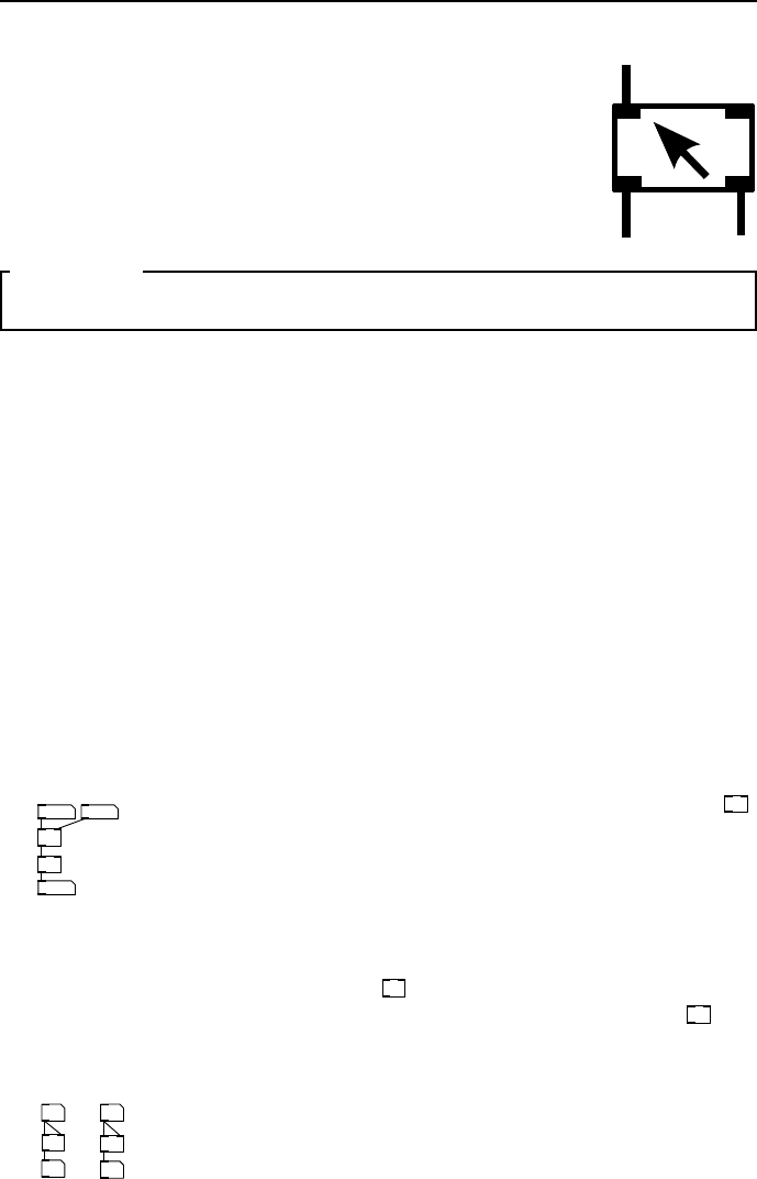
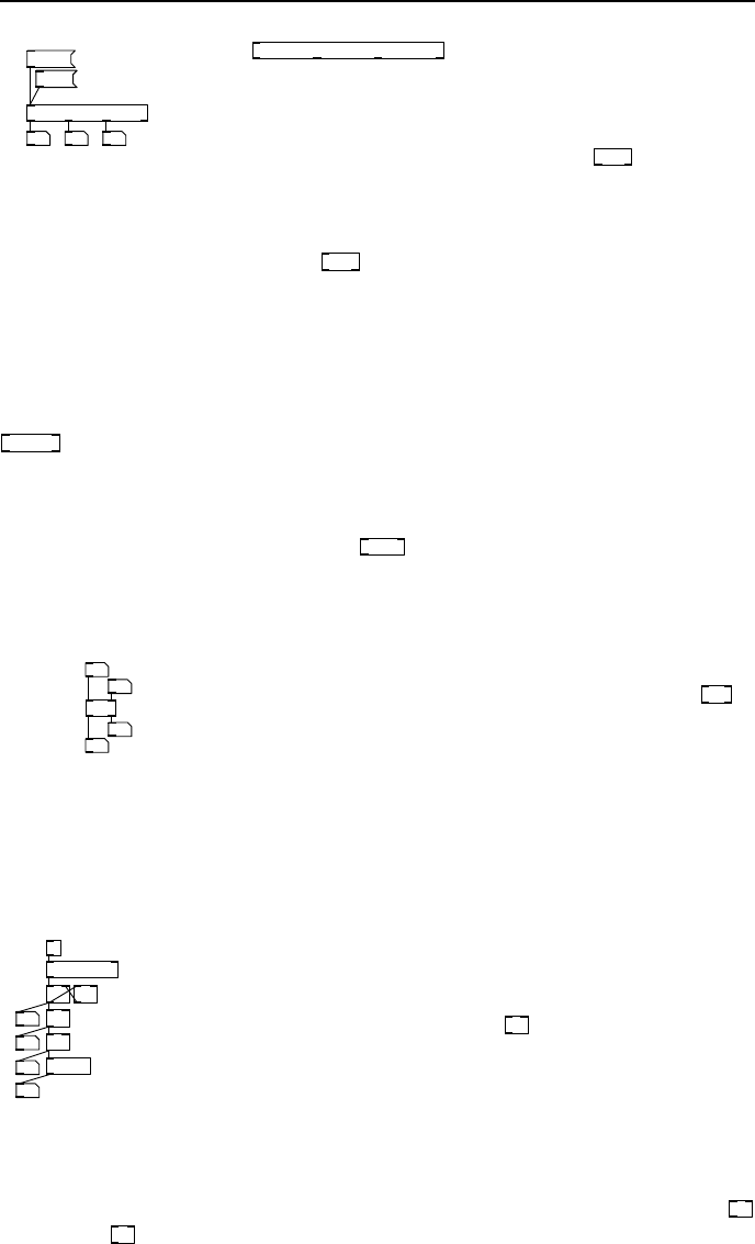
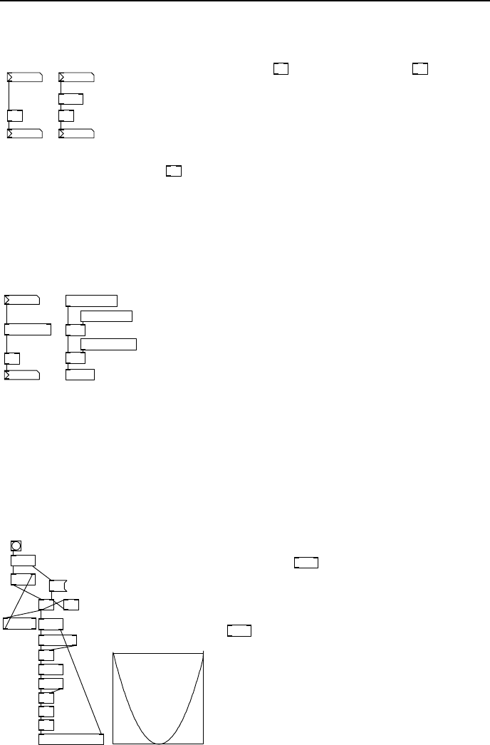
fig 3.1: Hot and
cold inlets
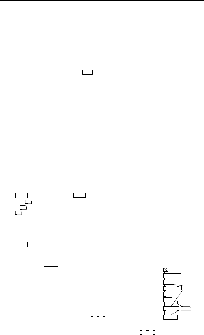
In Fig. 3 .1 a new number box is added to right inlet of
*
.
This new va lue represents a constant multiplier k so we can
compute y = kx +3. It overridesthe 5 given as an initial
parameter when changed. In Fig. 3.1 it’s set to 3 so we have
y =3x +3. Experiment setting it to another value and
then changing the left number box. Notice that changes to
the right num ber box don’t immediately effect the output,
because it connects to the cold inlet of
*
,butchangestotheleftnumberbox
cause the output to change, because it is connected to the hot inlet of
*
.
Bad evaluat ion order
16
15
+
8
+
good
bad
8
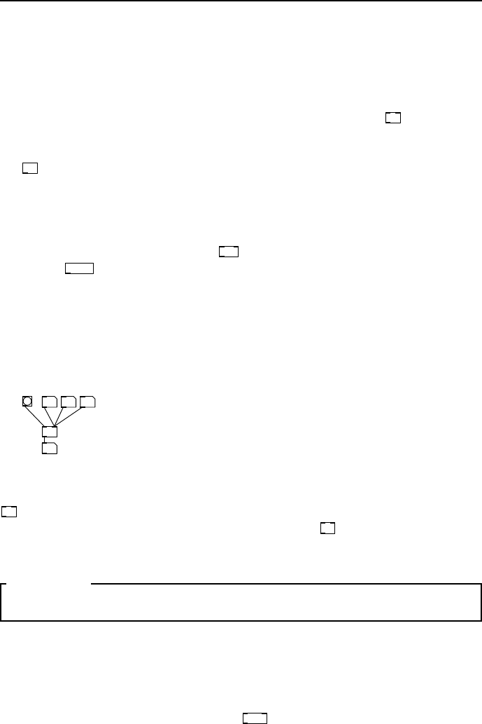
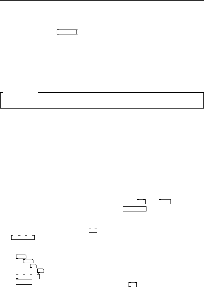
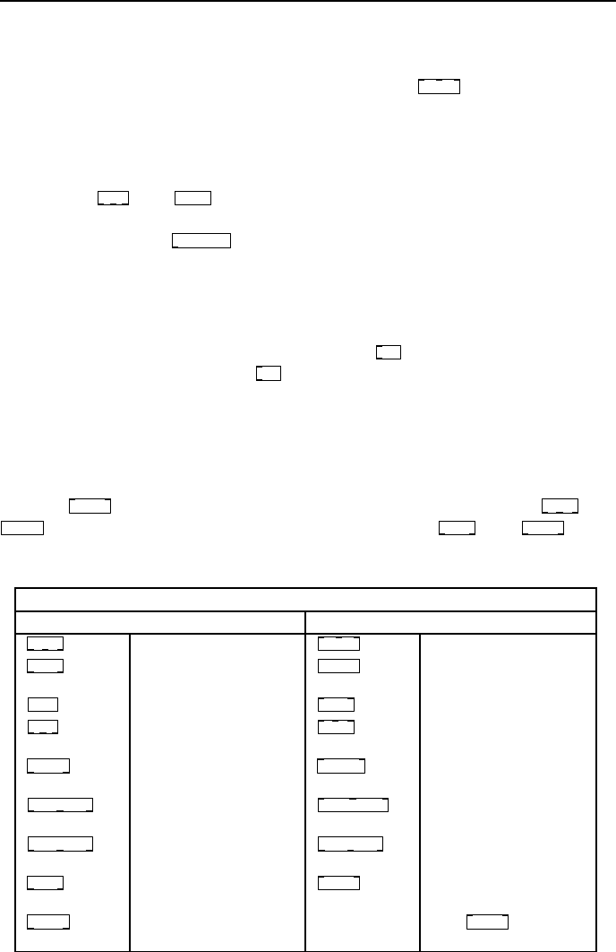
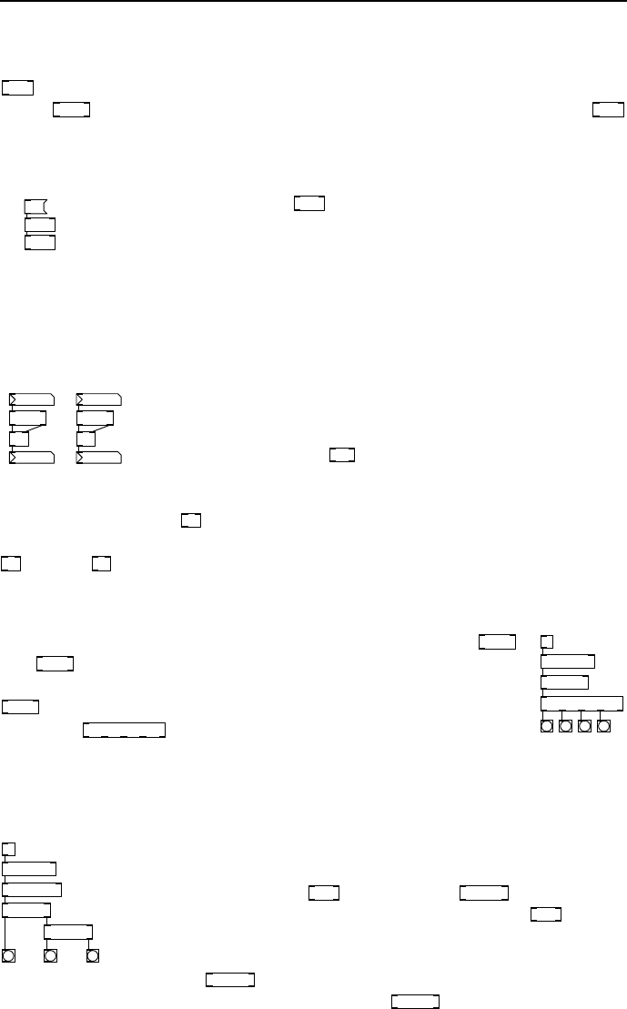
fig 3.2: Bad ordering
Aproblemariseswhenmessagesfanoutfromasingle
outlet into other operations. Look at the two patches in
Fig. 3.2. Can you tell the difference? It is impossible
to tell just by looking that one is a working patc h and
the other contains a nasty error. Each is an attempt to
double the value of a number by connecting it to both

22 Using Pure Data
sides of a
+
.Whenconnectionsaremadethiswaythebehaviourisundefined,
but usually happens in the order the connections were made. The first one
works because the right (cold) inlet was connected before theleft(hot)one.
In the second patch the arriving number is added to the last number received
because the hot inlet is addressed first. Try making these patches by connecting
the inlets to
+
in a different or der. If you accidenta lly crea te errors this way
they are hard to debug.
Trigger ob jects
Atriggerisanobjectthatsplitsamessageupintopartsandsends them over
several outlets in o r der. It solves the evaluation order problem by making the
order explicit.
20
+
10
t f f
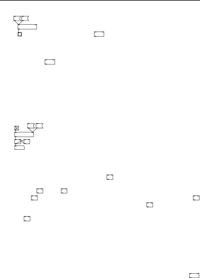
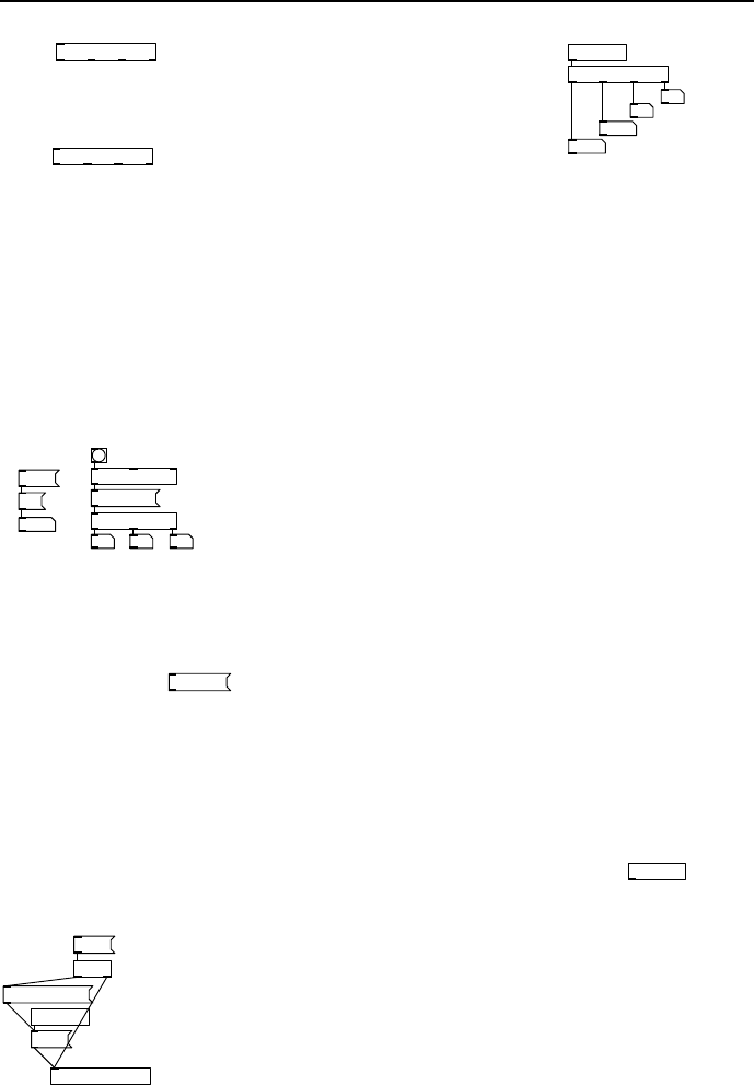
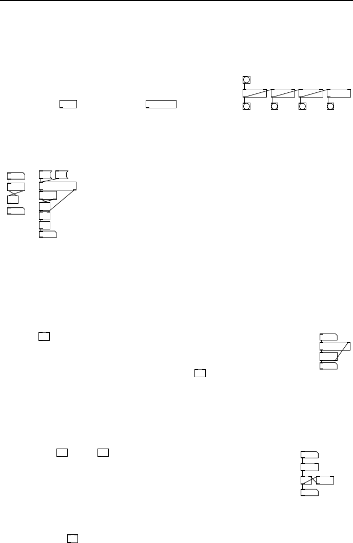
fig 3.3: Ordering with
trigger
The order of output is right to left, so a
trigger bang float
object outputs a float on the right outlet first, then a
bang on the left one. This can be abbreviated a s
t b f
.
Proper use of triggers ensures correct op eration of units
further down the connection graph. The arguments to a
trigger may be s for sy mbol, f for float, b for bang, p
for pointers and a for any. The “any” type will pass lists
and pointers to o. The patch in Fig. 3.3 always works correctly, whatever order
you connect to the
+
inlets. The float from the right outlet of
t f f
is always
sent to the cold inlet of
+
first, and the left one to the hot inlet afterwards.
Making cold inlets hot
7
+
3
t b f
4
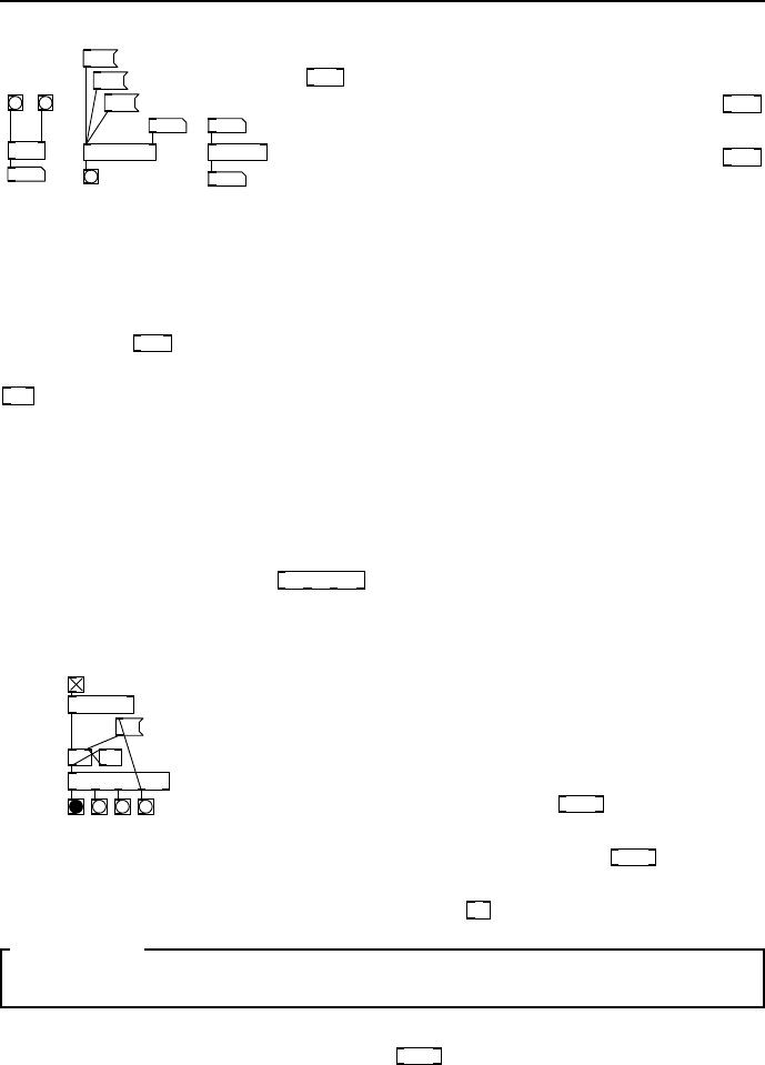
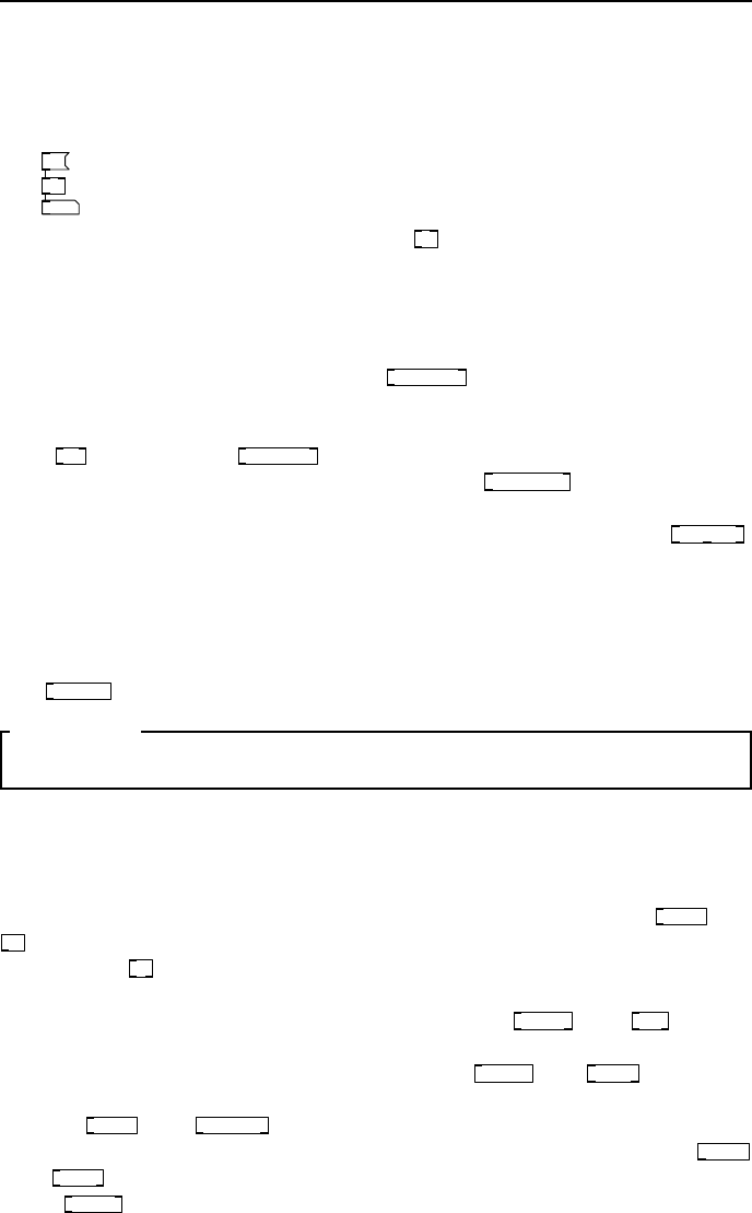
fig 3.4: Warming an
inlet
An immediate use for our new knowledge of triggers is to
make an arithmetic operator like
+
respond to either of
its inlets immediately. Make the patch shown in Fig. 3.4
and try changing the number boxes. When the left one is
changed it sends a float number message to the left (hot)
inlet which updates the output as usua l. But now, when
you change the right number box it is split by
t b f
into
two messages, a float which is sent to the cold (right) inlet of
+
,andabang,
which is sent to the hot inlet immediately afterwards. When itreceivesabang
on its hot inlet
+
computes the sum of the two numb ers last seen on its inlets,
which gives the right result.
Float objects
The object
f
is very common. A shorthand for
float
,whichyoucanalsouse
if you like to make things clearer, it holds the value of a single floating point
number. Y ou might like to think of it as a variable, a temporaryplacetostorea
number. There are two inlets on
f
,therightmostonewillsetthevalueofthe
object, and the leftmost one will both set the value and/or output it depending
on what message it receives. If it receives a bang message it will just output
whatever value is currently stored, but if the message is a float it will override
3.2 Working with time and events 23
the currently stored value with a new float and immediately output that. This
gives us a way to both set and query the object contents.
Int objects
Although we hav e noted that integers don’t really exist in Pd,notinawaythat
aprogrammerwouldunderstand,wholenumberscertainlydo.
int
stores a float
as if it were an integer in that it provides a rounding (truncation) function of
any extra decimal places. Thus 1.6789 becomes 1.0000, equal to 1, when passed
to
int
.
Symbol and list objects
As for num bers there are likewise object boxes to store lists and symb ols in a
temporary location. Both work just like their numerical counterparts. A list
can be given to the right inlet of
list
and recalled by banging the left inlet.
Similarly
symbol
can s tore a single sy mbol until it is needed.
Merging message connections
When several message connections are all connected to the same inlet that’s
fine. The object will process each of them as they arrive, though it’s up to you
to ensure that they arrive in the right order to do what you expect. Be aware
of race hazards when the sequence is important.
11
10
f
11 12
fig 3.5: Messages to
same inlet
Messages arriving from different so ur ces at the same hot
inlet have no effect on each another, they remain separa te
and are simply interleaved in the order they arrive, each
producing output. But be mindful that wher e several
connections are made to a cold inlet only the last one
to arrive will be relevant. Eac h of the number boxes in
Fig. 3.5 connects to the same cold inlet of the float box
f
and a bang button to the hot inlet. Whenever the bang button is pressed
the output will be whatever is currently stored in
f
, which will be the last
number box changed. Which number box was updated last in Fig. 3.5? It was
the middle one with a value of 11.
SECTION 3.2
Working with time and events
With our simple knowledge of objects we can now begin making patches that
work on functions of time, the basis of all sound and m usic.
Metronome
Perhaps the most important primitive operation is to get a beat or timebase.
To get a regular series of bang events
metro
provides a clock. Tempo is given
as a p eriod in milliseconds rather than beats p er minute (as isusualwithmost
music programs).
24 Using Pure Data
1 0
metro 1000
fig 3.6: Metronome
The left inlet toggles the metronome on and off when it
receives a 1 or 0, while the right one allows you to set
the period. Periods that are fractions of a millisecond are
allowed. The
metro
emits a bang as soo n as it is switched
on and the following bang occurs after the time perio d.
In Fig. 3.6 the time period is 1000ms, (equal to 1 second).
The bang button here is used as an indicator. As soon as you click the message
box to send 1 to
metro
it begins sending out bangs which make the bang button
flash once per second, until you send a 0 message to tur n it off.
Acountertimebase
We could use the metronome to trigger a sound repeatedly, likeasteadydrum
beat, but on their own a series of bang events aren’t much use. Although
they are separated in time we cannot keep track of time this waybecausebang
messages contain no information.
metro 1000
500 250
f 0 + 1
24
fig 3.7: Counter
In Fig. 3.7 we see the metronome again. This time the
messages to start and stop it have been convenien t ly re-
placed by a toggle switch. I have also added two new
messages whic h can change the period and thus make
the metronome faster or slower. The interesting part is
just below the metronome. A float box receives bang
messages on its hot inlet. Its initial value is 0 so upon
receiving the first bang message it outputs a float number 0 which the number
box then displays. Were it not for the
+ 1
object the patch would continue
outputting 0 once p er beat forever. However, lo ok closely at the wiring of these
two objects,
f
and
+ 1
are connected to form an incr ementor or counter.
Each time
f
recieves a bang it ouputs the number currently stored to
+ 1
which adds 1 to it. This is fed back into the cold inlet of
f
which updates its
value, now 1. The next time a bang arrives 1 is output, which goes r ound again,
through
+ 1
and becomes 2. This rep eats as long as bang messages arrive, each
time the output increases by 1. If you start the metronome in Fig. 3.7 you will
see the number box slowly counting up, once per second. Clicking the mes sage
boxes to change the period will make it count up faster with a 500ms delay
between beats (twice per second), or still faster at 4 times per second (25 0ms
period).
Time objects
Three related objects help us manipulate time in the message domain.
timer
accurately measures the interval between receiving two bangmessages,thefirst
on its left inlet and the second on its right inlet. It is shown on the left of
Fig. 3.8.
3.3 Data flow control 25
bang
delay 1000
stop
2000
timer
214.6
pipe 300
0
0
250
fig 3.8: Time objects
Clicking the first bang button will reset and start
timer
and then hitting the second one will out-
put the time elapsed (in ms). Notice that
timer
is unusual, it’s one of the few objects wher e the
right inlet behaves as the hot control.
delay
shown in the middle of Fig. 3.8 will o utput a
single bang message a certain time period after
receiving a bang on its left inlet. This interval
is set by its first argument or right inlet, or by the value of a float arriving at its
left inlet, so there are three ways of setting the time delay. If a new bang arrives
any p ending one is cancelled and a new delay is initiated. If a stop message
arrives then
delay
is reset and all pending events are cancelled. Sometimes we
want to delay a stream of number messages by a fixed amount, which is where
pipe
comes in. This allocates a memory buffer that moves messages from its
inlet to its outlet, taking a time set by its first argument or second inlet. If you
change the top number box of the right patch in Fig. 3.8 you willseethelower
number box follow it, but lagging behind by 300ms.
Select
This object outputs a bang o n one of its outlets matching s omething in its
argument list. For example
select 2 4 6
will output a bang on its second outlet if
it receives a number 4, or on its third outlet when a number 6 arrives. Messages
that do not match any argument are passed through to the righ tmost outlet.
f 0 + 1
0
select 0 1 2 3
metro 300
fig 3.9: Simple sequencer
This makes it rather easy to begin making sim-
ple sequences. The patch in Fig. 3.9 cycles around
four steps blinking each bang button in turn. It
is a metronome running with a 300ms period and
acounter. Onthefirststepthecounterholds0,
and when this is output to
select
it sends a bang
to its first outlet which matches 0. As the counter
increments, successive outlets of
select
produce a
bang, until the fourth one is reached. When this happens a message containing
0istriggeredwhichfeedsintothecoldinletof
f
resetting the counter to 0.
SECTION 3.3
Data flow control
In this section are a few common objects used to co ntrol the flowofdata
around patches. As you have just seen
select
can send bang messages along a
choice of connections, so it gives us a kind of selective flow.
Route
Route behaves in a similar fashion to select, only it operatesonlists. Ifthefirst
element of a list matches an argument the remainder of the listispassedtothe
corresponding outlet.
26 Using Pure Data
route vcf vco vca
20 0 5
vcf 20
vca 5
fig 3.10: Routing val-
ues
So,
route badger mushroom snake
will send 20.0toitsthirdoutlet
when it receives the message {snake 20 }.Nonmatch-
ing lists are pass ed unchanged to the rightmo st outlet.
Arguments can be numbers or symbols, but we tend to
use symbols because a combination of
route
with lists is
agreatwaytogiveparametersnamessowedon’tfor-
get what they are for. We have a few named values in
Fig. 3.10 for synthesiser controls. Each message box contains a two element
list, a name-value pair. When
route
encounters o ne that matches one of its
arguments it sends it to the correct number box.
Moses
A“streamsplitter”whichsendsnumbersbelowathresholdtoits left outlet,
and numbers greater than or equal to the threshold to the rightoutlet. The
threshold is set by the first argument or a value appearing on the right inlet.
moses 20
splits any incoming numbers at 20.0
Spigot
This is a switch that can control any stream of messages including lists and
symbols. A zero on the right inlet of
spigot
stops any messages on the left inlet
passing to the outlet. Any non-zero number turns the spigot on.
Swap
swap
15
20
20
15
fig 3.11: Swapping values
It mig ht look like a very trivial thing to do, and you
may ask - why not just cross two wires? In fact
swap
is
really useful object. It just exchanges the two values
on its inlets and passes them to its outlets, but it can
take an argument so it always exchanges a num ber
with a constant. It’s useful when this co ns ta nt is 1 as
shown later for calculating complement 1 − x and inverse 1/x of a numb er, or
where it is 100 for calculating values as a percent.
Change
f 0 + 1
/ 2
int
3
1.5
change
1
1
metro 1000
fig 3.12: Pass v al-
ues that change
This is useful if we have a stream of numbers, p e rhaps from a
physical controller like a joystick that is polled at regularin-
tervals, but we only want to know values when they change.
It is frequently seen preceded by
int
to denoise a jittery sig-
nal or when dividing timebases. In Fig. 3.12 we see a counter
that has been stopped after reaching 3. The components be-
low it are designed to divide the timebase in half. That is
to say, for a sequence {1, 2, 3, 4, 5, 6 ...} we will get
{1, 2, 3 ...}.Thereshouldbehalfasmanynumbersin
the output during the same time interval. In other words the output changes
half as often as the input. Since the counter has just passed 3 the output of
/
is 1 .5and
int
truncates this to 1. But this is the second time we have seen 1

3.3 Data flow control 27
appear, since the same number was sent when the input was 2. Without using
change
we would get {1, 1, 2, 2, 3, 3 ...} as output.
Send and receive objects
send mungo send midge
29 9 69
s mary
fig 3.13: Sends
Very useful for when patches get too visually dense,
or when you are working with patches spread across
many canvases.
send
and
receive
objects, abbreviated
as
s
and
r
work as named pairs. Anything that
goes into the send unit is transmitted by an invisible wire andappearsimmedi-
ately on the receiver, so whatever goes into
send bob
reappears at
receive bob
.
29 9 69
receive mary r midger mungo
fig 3.14: Receives
Matching sends and receives have global names by
default and can exist in differe nt canvases loaded at
the same time. So if the
receive
objects in Fig. 3.14
are in a different patch they will still pick up the
send values from Fig. 3.13. The relationship is o ne to many, soonlyonesend
can have a particular name but can be picked up by multiple
receive
objects
with the same name. In the latest versions of Pd the destination is dynamic
and can b e changed by a message on the right inlet.
Broadcast messages
As w e have just seen there is an “invisible” environment through which messages
may travel as well as through wires. A message box cont aining amessagethat
begins with a semicolon is broadcast and Pd will route it to any destination that
matches the first symbol. This way, activating the message box
; foo 20
is the
same as sending a float message with a value of 20 to the object
s foo
.
Special message destinations
This method ca n be used to address arrays with special commands, to talk to
GUI elements that have a defined receive symbol or as an alternative way to talk
to
receive
objects. If you want to change the size of arrays dynamically they
recognise a special resize message. There is also a special destination (which
always exists) called pd which is the audio engine. It can act on broa dcast
messages like
; pd dsp 1
to turn on the audio computation from a patch. Some
examples are shown in Fig. 3.15
;
a1 sinesum 64 0.2 0.2
gain
64.00
;
gain 64
;
a2 resize 128;
a2 sinesum 128 0.1 0.2;
a2 normalize
a1
a2
fig 3.15: Special message broadcasts
28 Using Pure Data
Message sequences
Several messages can be stored in the same message-box as a sequence if sepa-
rated by commas, so
2, 3, 4, 5
is a message-box that will send four values one
after another when clicked or banged. This happens instantly(inlogical time).
This is often confusing to b e ginners when comparing sequences to lists. When
you send the contents of a message box containing a sequence all the elements
are sent in one go, but as separate messages in a stream. Lists on the other
hand, which are not separated by commas, also send all the elements at the
same time, but as a single list message. Lists and sequences can be mixed, so a
message box might contain a sequence of lists.
SECTION 3.4
List objects and operation s
Lists can be quite an advanced topic and we could devote an entire chapter
to this subject. Pd has all the capabilities of a full programming language like
LISP, using only list oper ations, but like that languag e all the more complex
functions are defined in terms of just a few intrinsic operations and abstrac-
tions. The list-abs collection by Frank Barknecht and others is available in
pd-extended. It contains scores of advanced operations like sorting, reversing,
inserting, searching and performing conditional operations on every element of
alist. Herewewilllookatahandfulofverysimpleobjectsandleaveitas
an exercise to the reader to research the more advanced capabilities of lists for
building sequencers and data analysis tools.
Packing and unpacking lists
The usual way to create and disasse mble lists is to use
pack
and
unpack
.Arguments
are given to each which are type identifiers, so
pack f f f f
is an object that w ill
wrap up four floats given on its inlets into a s ingle list. They should be presented
in right to left order so that the hot inlet is filled last. You can also give float
values directly as arguments of a
pack
object where you want them to b e fixed,
so
pack 1 f f 4
is legal, the first and last list elements will be 1 and 4 unless
over-ridden by the inlets, and the t wo middle ones will be variable.
pack s s f f
foo
bar
2
1
s packed
fig 3.16: List packing
Start by changing the right number in Fig. 3.16,
then the one to its left, then click on the sym-
bol boxes and type a short string before hitting
RETURN.Whenyouenterthelastsymbolconnected
to the hot inlet of
pack
you will see the data re-
ceived by Fig. 3.17 appear in the display boxes
after it is unpacked.
3.4 List objects and operations 29
foo
bar
2
1
r packed
unpack s s f f
fig 3.17: List unpacking
The
unpack s s f f
will expect two symbols and two
floats and send them to its four outlets. Items are
packed and unpacked in the sequence given in the
list, but in right to left order. That means the floats
from
unpack s s f f
will appear first, starting with the
rightmost one, then the two symbols ending on the
leftmost one. Of course this happens so quickly you
cannot see the ordering, but it makes sense to happen this way so that if you are
unpacking data, changing it and re-packing into a list everything occurs in the
right order. Note that the types of data in the list must match the arguments
of each object. Unless you use the a (any) type Pd will complain if you try to
pack or unpack a mismatched type.
Substitutions
$1
5
5 6 7
$3 $1 $2
pack 5 10 15
unpack f f f
15 5 10
fig 3.18: Dollar substitu-
tion.
Amessageboxcanalsoactasatemplate. When
an item in a message b ox is written $1 it behaves
as an empty slot that assumes the value of the first
element of a given list. Each of the dollar arguments
$1, $2 and so on, are replaced by the correspond-
ing item in the input list. The message box then
sends the new message with any slots filled in. List
elements can be substituted in multiple positions as
seen in Fig. 3.18. The list {51015} becomes {15 5 10 } when put through
the substitution
$3 $1 $2
.
Persistence
You will often want to set up a patch so it’s in a certain state when loaded.
It’s possible to tell most GUI objects to output the last valuetheyhadwhen
the patch was saved. You can do this by setting the init checkbox in the
properties panel. But what if the data you want to keep comes from another
source, like an external MIDI fader board? A useful o bject is
loadbang
which
generates a bang message as soon as the patch loads.
4 6 8
set $1 $2 $3
loadbang
pd synthesiser
t a a
4 6 8
fig 3.19: Persistence using
messages
You can use this in combination with a message
box to initialise some values. The contents of message
boxes are saved and loaded with the patch. When you
need to stop working o n a project but have it load the
last state next time around then list data can be saved
in the patch with a message box by using the special
set prefix. If a message box rec e ives a list prefixed by
set it will be filled with the list, but not immediately
ouput it. The arrangement in Fig. 3.19 is used to keep
a3elementlistforpd synthesiser in a message box that will be saved with
the patch, then generate it to initialise the synthesiser again when the patch is
reloaded.
30 Using Pure Data
List distribution
An object with 2 or more message inlets will distribute a list of parameters to
all inlets using only the first inlet.
2
9 7
-
fig 3.20: Dis-
tribution
The numbe r of elements in the list must match the number of
inlets and their ty pes must be compatible. In Fig. 3.20 a message
box contains a list of two numbers, 9 and 7. When a pair of
values like this are sent to
-
with its right inlet unconnected
they are spread over the two inlets, in the order they appear,
thus 9 −7=2.
More advanced list operations
To concatenate two lists together we use
list append
.Ittakestwolistsandcreates
anewonewiththesecondlistattachedtotheendofthefirst. Ifgivenan
argument it will append this to every list it receives. It may be worth knowing
that
list
is an alias for
list append
.Youcanchoosetotypeineitherinorderto
make it clearer what you are doing. Very similar is
list prepend
which does a lmo st
the same, but returns a new list with the argument or list at thesecondinlet
concatenated to the beginning. For disassembling lists we can use
list split
.
This takes a list on its left inlet and a number on the right inlet (or as an
argument) which indicates the position to split the list. It produces two new
lists, one containing elements below the split point appearsontheleftoutlet,
and the remainder of the list app ears on the right. If the supplied list is shorter
than the split number then the entire list is passed unchangedtotherightoutlet.
The
list trim
object strips off any selector at the start leaving the raw elemen t s.
SECTION 3.5
Input and output
There are plenty of objects in Pd for reading keyboards, mice,systemtimers,
serial ports and USB. There’s not enough room in this book to domuchmore
than summarise them, so please refer to the Pd online documentation for your
platform. Many of these are available only as external objects, but several are
built into Pd core. Some depend on the platform used, for e xample
comport
and
key
are only available on Linux and MacOS. One of the most useful externals
av ailable is
hid
which is the “human interface device”. With this you can
connect joysticks, game controllers, dance mats, steering wheels, graphics tablets
and all kinds of fun things. File IO is available using
textfile
and
qlist
objects,
objects are available to make database transactions to MySQL, and of course
audio file IO is simple using a range of objects like
writesf~
and
readsf~
.MIDIfiles
can be imported a nd written with similar objects. Network access is available
through
netsend
and
netreceive
which offer UDP or TCP services. Open Sound
Control is available using the external OSC library by MartinPeachor
dumpOSC
and
sendOSC
objects. You can even generate or open compressed audio streams
using
mp3cast~
and similar externals, and you can run code from other languages
like pytho n and lua. A popular hardware peripheral for use in combination with
3.5 Input and output 31
Pd is the Arduino board which gives a number of buffered analog and digital
lines, serial and parallel, for robotics and control applications. Nearly all of this
is quite beyond the scope of this book. The way you set up your DAW and buil d
your sound design studio is an individual matter, but Pd should not disappoint
you when it comes to I/O connectivity . We will now look at a few common
input and output channels.
The print object
Where would we be without a
print
object? Not much use for making sound,
but vital for debugging patches. Message domain data is dumped to the console
so you can see what is going on. You can give it a non-numerical argument
which will prefix any output and make it easier to find in a long printout.
MIDI
When working with musical keyboards there are objects to helpintegratethese
devices so you can build patches with traditional synthesiser and sampler be-
haviours. For sound design this is gr e at for attaching MIDI fader boards to con-
trol parameters, and of course musical interface devices like breath controllers
and MIDI guitars can b e used. Hook up any MIDI source to Pd by activating a
MIDI device from the Media->MIDI menu (you can check this is working from
Media->Test Audio and MIDI).
Notes in
You can create single events to trigger from individual keys,orhavelayersand
velocity fades by adding extra logic.
notein
60 note
127 velocity
1 channel
fig 3.21: MIDI note in
The
notein
object produces note number, velocity and
channel v alues on its left, middle and right outlets. Y ou
may assign an object to listen to only one channel by giv-
ing it an argument from 1 to 15. Remember that note-off
messages are equivalent to a note-on with zero velocity in
many MIDI implementations and Pd follows this method.
You therefore need to add extra logic before connecting an oscillator o r sample
player to
notein
so that zero va lued MIDI notes are not played.
Notes out
makenote
metro 200
+ 48
random 3
* 12
t b b
random 127
notelength
984.1
noteout
fig 3.22: MIDI
note generation
Another object
noteout
sends MIDI to external devices. The
first, second and third inlets set note number, velocity and
channel respectively. The channel is 1 by default. Make
sure you have something connected that can play back MIDI
and set the patch shown in Fig. 3.22 running with its toggle
switch. Every 2 00 ms it produces a C on a random octave
with a ra ndom ve locity value between 0 a nd 127. Without
further ado these could be sent to
noteout
,butitwouldcause
each MIDI note to “hang”, since we never send a note-off
message. To properly construct MIDI notes you need
makenote
32 Using Pure Data
which takes a note-number and velocity, and a duration (in milliseconds) as its
third argument. After the duration has expired it automatically adds a note-off.
If more than one physical MIDI port is enabled then
noteout
sends channels 1 to
16 to port 1 and channels 17 to 32 to port 2 etc.
Continuous controllers
Two MIDI input/output objects are provided to receive and send continuous
controllers,
ctlin
and
ctlout
.Theirthreeconnectionsprovide,orletyouset,the
controller value, controller number and MIDI channel. They can be instantiated
with arguments, so
ctlin 10 1
picks up controller 10 (pan position) on MIDI
channel 1.
MIDI to Frequency
Two numerical conversion utilities are provided to convert between MIDI note
numbers and Hz. To get from MIDI to Hz use
mtof
.Toconvertafrequencyin
Hz to a MIDI note number use
ftom
.
Other MIDI objects
For pitchb end, program changes, system exclusive, aftertouch and other MIDI
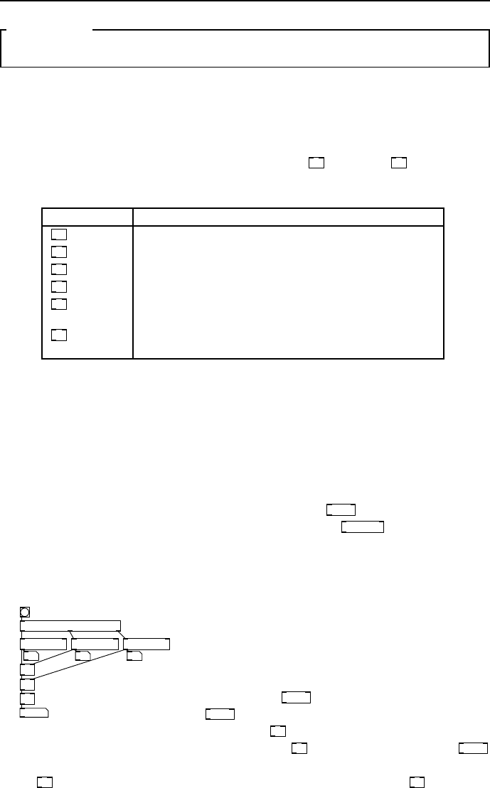
functions you may use any of the objects summarised in Tbl. 3.23. System
exclusive messages may be sent by ha nd crafting raw MIDI bytesandoutputting
via the
midiout
object. Most follow the inlet and outlet template of
notein
and
noteout
having a channel as the last argument, except for
midiin
and
sysexin
which
receive omni (all channels) data.
MIDI in object MIDI out object
Object Function Object Function
notein
Get note data
noteout
Send note data.
bendin
Get pitchbend data
−63 to +64
bendout
Send pitchbend data
−64 to +64.
pgmin
Get program changes.
pgmout
Send program change s.
ctlin
Get con tinuous con-
troller messages.
ctlout
Send cont inuous con-
troller messages.
touchin
Get channel aftertouch
data.
touchout
Send c hanne l after-
touch data.
polytouchin
Polyphonic touch data
in
polytouchout
Polyphonic touch out-
put
polytouchin
Send polyphonic after-
touch.
polytouchin
Get polyphonic after-
touch.
midiin
Get unformatted raw
MIDI
midiout
Send raw MIDI to de-
vice.
sysexin
Get system exclusive
data
No output
counterpart
Use
midiout
object
fig 3.23: List of MIDI objects
3.6 Working with numbers 33
SECTION 3.6
Working with numbers
Arithmetic objects
Objects that operate on ordinary numb ers to provide basic maths functions are
summarised in Tbl. 3.24 All have hot left and cold right inletsandalltakeone
argument that initialises the value otherwise received on the right inlet. Note
the difference between arithmetic division with
/
and the
div
object. The
modulo operator gives the remainder of dividing the left number by the right.
Object Function
+
Add two floating point numbers
-
Subtract number on right inlet from number on left inlet
/
Divide lefthand number by number on right inlet
*
Multiply two floating p oint numbers
div
Integer divide, how many times the number on the right
inlet divides exactly into the number on the left inlet
mod
Modulo, the smallest remainder of dividing the left num-
ber into any integer multiple of the right number
fig 3.24: Table of message arithmeti c op erators
Trigonometric maths ob jects
A summary of higher maths functions is given in Tbl. 3.25.
Random numbers
Ausefulabilityistomakerandomnumbers. The
random
object gives integers
over the range given by its argument including zero, so
random 10
gives 10 p ossible
values from 0 to 9.
Arithmetic example
random 100 random 100 random 100
+
96 12 88
trigger bang bang bang
+
/ 3
65.333
fig 3.26: Mean of three random
floats
An example is given in Fig. 3.26 to show cor-
rect ordering in a patch to calculate the mean
of three random numbers. We don’t have to
make every inlet hot, just ensure that ev ery-
thing arrives in the correct sequence by trig-
gering the
random
objects properly. The first
random
(on the right) supplies the cold inlet of
the lower
+
,themiddleonetothecoldinlet
of the upper
+
.Whenthefinal(left)
random
is generated it passes to the hot inlet of the
first
+
,whichcomputesthesumandpassesittothesecond
+
hot inlet.
Finally we divide by 3 to get the mean value.

34 Using Pure Data
Object Function
cos
The cosine of a number given in radians. Domain: −π/2
to +π/2. Range: −1.0 to +1.0.
sin
The si ne of a number in radians, domain −π/2 to +
π/2, range −1.0 to +1.0
tan
Tangent of number given in radians. Range: 0.0 to ∞
at ±π/2
atan
Arctangent of any number in domain ±∞ Range: ±π/2
atan2
Arctangent of the quotient of two numb ers in Carte-
sian plane. Domain: any floats representing X, Y pair.
Range: angle in radians ±π
exp
Exponential function e
x
for any number. Range 0.0
to ∞
log
Natural l og (base e)ofanynumber. Domain: 0.0
to ∞.Range:±∞ (−∞ is −1000.0)
abs
Absolute value of any number. Domain ±∞.Range0.0
to ∞
sqrt
The square root of any positive number. Domain
0.0 to ∞
pow
Exponentiate the left inlet to the power of the right inlet.
Domain: positive left values only.
fig 3.25: Table of message trigonometric and higher math operators
Comparative objects
In Tbl. 3.27 you can see a summary of comparative objects. Output is either
1or0dependingonwhetherthecomparisonistrueorfalse. Allhavehotleft
inlets and cold right inlets and can take an argument to initialise the righthand
value.
Object Function
>
True if the number at the left inlet is greater than the
right inlet.
<
True if the number at the left inlet is less than the right
inlet.
>=
True if the numb er at the left inlet is greater than or
equal to the right inlet.
<=
True if the number at the left inlet is less than or equal
to the righ t inlet.
==
True if the number at the left inlet is equal to the right
inlet.
!=
True if the number at the left inlet is not equal to the
right inlet
fig 3.27: List of comparative operators
3.7 Common idioms 35
Boolean logical objects
There are a whole bunch of logical objects in Pd including bitwise operations
that work exactly like C code. Most of them aren’t of much interest to us in this
book, but we will mention the two important ones
||
and
&&
.Theoutputof
||
,logicalOR,istrueifeitherofitsinputsaretrue. Theoutput of
&&
,logical
AND, is true only when both its inputs are true. In Pd any non-zero number is
“true”, so the logical inverter or “not” function is unnecessary b ecause there are
many wa ys of achieving this using other objects. For example,youcanmakea
logical inverter by using
!=
with 1 as its argument.
SECTION 3.7
Common idioms
There are design patterns that crop up frequently in all typesofprogram-
ming. Later we will look at abstraction and how to encapsulatecodeintonew
objects so you don’t find yourself writing the same thing againandagain. Here
Iwillintroduceafewverycommonpatterns.
Constrained counting
metro 500
f
mod 8
+ 1
mod 4
mod 3
13
trigger f f f
7
fig 3.28:
Constrained
counter.
We have already seen how to make a co unter by repeatedly in-
crementing the value stored in a float box. To turn an increasing
or decreasing counter into a cycle for rep eated sequences there
is an easier way than resetting the counter when it matches
an upper limit, we wrap the numbers using
mod
.Byinserting
mod
into the feedback path before the increment we can ensure
the counter stays bounded. Further
mod
units can be added to
the number stream to generate polyrhythmic sequences. You
will frequently see variations on the idiom shown in Fig. 3.28.
This is the way we produce multi-rate timebases for musical
sequencers, ro lling objects or machine so unds that have complex repetitive pat-
terns.
Accumulator
+ f
0
1 -1
fig 3.29:
Accumu-
lator.
Asimilarconstructtoacounteristheaccumulatororintegrator.
This reverses the p ositions of
f
and
+
to create an integrator that
stores the sum of all previous number messages sent to it. Suchan
arrangement is useful for turning “up and down” messages froman
input controller into a position. Whether to use a counter or accu-
mulator is a subtle choice. Although you can change the increment
step of the counter by placing a new value on the r ight inlet of
+
it will not
take effect until the previous value in
f
has been used. An accumulator on the
other hand can be made to jump different intervals immediatelybythevalue
sent to it. Note the important difference, an accumulator takes floats as an
input while a counter takes bang messages.
36 Using Pure Data
Rounding
+ 0.5
i
0.51
1
0.99
0
int
fig 3.30: Rounding
An in teger function,
int
,alsoabbreviated
i
gives the
whole part of a floating point number. This is a trun-
cation,whichjustthrowsawayanydecimaldigits. For
positive numbers it gives the floor function, written ⌊x⌋
which is the integer less than or equal to the input value.
But take note of what happens for negative values, apply-
ing
int
to −3.4willgive3.0, an integer greater than or
equal to the input. Truncation is shown on the left of Fig. 3.30. To get areg-
ular rounding for positive numbers, to pick the closest integer, use the method
shown o n the right side of Fig. 3 .30 . This will return 1 for an input of 0.5or
more and 0 for an input of 0.49999999 or less.
Scaling
inlet value
inlet scale
inlet offset
outlet
127
9.999
+ 1
* 0.070866
* $1
+ $2
fig 3.31: Scaling
This is such a common idiom you will see it almost
everywhere. Given a range of values such as 0 to 127
we may wish to map this onto another set of v alues,
the domain, such as 1 to 10. This is the same as
changing the slope and zero intersect of a line following
y = mx + c.Toworkoutthevaluesyoufirstobtain
the bottom value or offset,inthiscase+1. Thena
multiplier value is needed to scale for the upper value, which given an input of
127 would satisfy 10 = 1 + 127x,somovingtheoffset we get 9 = 127x,and
dividing by 127 we get x =9/127 or x =0.070866. You can make a subpatch
or an abstraction for this as shown in Fig. 6.1, but since only two objects are
used it’s more sensible to do scaling and offset as you need it.
Looping with until
t b b
f + 1
0
until
t f f
cheby
tabwrite cheby
swap 129
-
/ 128
t f f
*
* 2
- 1
sel 256
fig 3.32: Using until
Unfortunately, because it must be designed
this way,
until
has the potential to cause
acompletesystemlock-up. Beverycare-
ful to understand what you are doing with
this. A bang message on the left inlet of
until
will set it producing bang messages
as fast as the system can handle! These do
not stop until abangmessageisreceivedon
the right inlet. Its purpose is to behave as a
fast loop construct performing message do-
main computation quickly. This way y ou
can fill an entire wavetable or calculate a
complex formula in the time it ta kes to pro-
cess a single audio block. Always make sure
the right inlet is connected to a valid terminating condition. In Fig. 3.32 you
can see an example that computes the second Chebyshev polynomial according
3.7 Common idioms 37
to y =2x
2
− 1fortherange−1.0to+1.0andfillsa256steptablewiththe
result. As soon as the bang button is pressed a counter is resettozeroandthen
until
begins sending out bangs. These cause the counter to rapidly increment
until
select
matches 256 whereupon a bang is sen t to the right inlet of
until
stopping the process. All this will happen in a fraction of a millisecond. Mean-
while we use the co unter output to calculate a Chebyshev curveandputitinto
the table.
256
min 1
until
fig 3.33: for
256
Asaferwaytouse
until
is shown in Fig. 3.33. If you know in
advance that you want to perform a fixed number of op erations
then use it like a for loop.Inthiscaseyoupassanon-zero
float to the left inlet. There is no terminating condition, it
stops when the specified number of bangs has been sent, 256
bangs in the example shown.
Message complement and inverse
swap 1
-
0.25
0.75
swap 1
0.5
2
/
fig 3.34: Message re-
ciprocal and inv erse
Here is how we obtain the number that is 1 −x for any x.
The complement of x is useful when you want to balance
two numbers so they add up to a constant value, such as
in panning. The
swap
object exchanges its inlet values,
or any left inlet value with its first argument. Therefore,
what happens with the left example of Fig. 3.34 is the
-
calculates 1 −x,whichforaninputof0.25 gives 0.75.
Similarly the inverse of a float message 1/x ca n be calculated by replacing the
-
with a
/
.
Random selection
metro 500
random 4
select 0 1 2 3
fig 3.35:
Random
select.
To choose one of several events at random a combination of
random
and
select
will ge nerate a bang message on the select outlet corre-
sponding to one of its a r g uments. With an initial argument of 4
random
produces a range of 4 random integer numbers starting at 0,
so we use
select 0 1 2 3
to select amongst them. Each has an equal
probability, so every outlet will be triggered 25% of the timeon
average.
Weighted random selection
metro 500
moses 10
random 100
moses 50
fig 3.36:
Weighted
random select.
Asimplewaytogetabunchofeventswithacertainproba-
bility distribution is to ge nerate uniformly distributed numbers
and stream them with
moses
.Forexample
moses 10
sends integers
greater than 9.0toitsrightoutlet. Acascadeof
moses
objects
will distribute them in a ratio over the combined outlets when
the sum of all ratios equals the range of random numbers. The
outlets of
moses 10
distribute the numbers in the ratio 1 : 9. When
the right outlet is further split by
moses 50
as in Fig. 3.36 numbers
in the range 0.0to100.0aresplitintheratio10:40:50,and
38 Using Pure Data
since the distribution of input number s is uniform they ar e sent to one of three
outlets with 10%, 40% and 50% probability.
Delay cascade
del 100 del 100 del 100 del 100
fig 3.37: Delay cascade.
Sometimes we want a quick succession of bangs in a
certain fixed timing pattern. An easy way to do this
is to cascade
delay
objects. Each
delay 100
in Fig. 3.37
adds a delay of 100 milliseconds. Notice the ab-
brieved form of the object name is used.
Last float and averages
t f b
f
3
2
t f b
f
12.5
+
/ 2
trigger f f
10 15
fig 3.38: Last value and av-
eraging
If you have a stream of float values and want to
keep the previous v alue to compare to the current
one then the idiom shown on the left of Fig. 3.38
will do the job. Notice how a trigger is employed to
first bang the last value stored in the float box and
then update it with the current value via the right
inlet. This can be turned into a simple “lowpass”
or averaging filter for float messages as shown on
the right of Fig. 3.38. If you add the previous value
to the current one and divide by two you obtain the average. In the example
shown the values were 1 0 followed by 1 5 , resulting in (10 + 15)/2=12.5.
Running maximum (or minimum)
t f f
9
max 1e-21
35
fig 3.39:
Biggest
so far
Giving
max
averysmallargumentandconnectingwhateverpasses
through it back to its right inlet gives us a way to keep track ofthe
largest value. In Fig. 3.39 the greatest past value in the stream ha s
been 35. Giving a very large argument to
min
provides the opposite
behaviour for tracking a lowest value. If you need to reset themax-
imum or minimum tracker just send a very large or small float value
to the cold inlet to start again.
Float lowpass
38
* 0.1
+ * 0.9
37.26
fig 3.40: Low
pass for floats
Using only
*
and
+
as shown in Fig. 3.40 we can low pass
filter a stream of float values. This is useful to smooth da ta from
an external controller where values are occasionally anomalous.
It follows the filter equation y
n
= Ax
n
+ Bx
n−1
.Thestrength
of the filter is set by the ratio A : B.BothA and B should b e
between 0.0and1.0andaddupto1.0. Note that this method
will not converge on the exact input value, so you might like to
follow it with
int
if you need numbers rounded to integer values.
39
CHAPTER 4
Pure Data Audio
SECTION 4.1
Audio objects
We have looked at Pd in enough detail now to move on to the next level.
You have a basic grasp of dataflow programming and know how to make patches
that process numbers and symbols. But why has no mention been made of audio
yet? Surely it is the main purpose of our study? The reason for this is that
audio signal processing is a little more complex in Pd than thenumbersand
symbols we have so far considered, so I wanted to leave this until now.
Audio connections
Ialreadymentionedthattheretwokindsofobjectsanddatafor messages
and signals. Corresponding to these there are two kinds of connections, audio
connections and message connections. There is no need to do anything special
to make the right kind of connection. When you connect two objects together
Pd will work out what typ e of outlet you are attempting to connect to what
kind of inlet and cr ea te the appropriate co nnection. If you try to connect an
audio signal to a message inlet, then Pd will not let you, or it will complain
if there is allowable but ambiguous connection. Audio objects alw ays have a
name ending with a tilde (∼)andtheconnectionsbetweenthemlookfatter
than ordinary message connections.
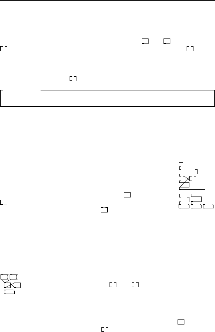
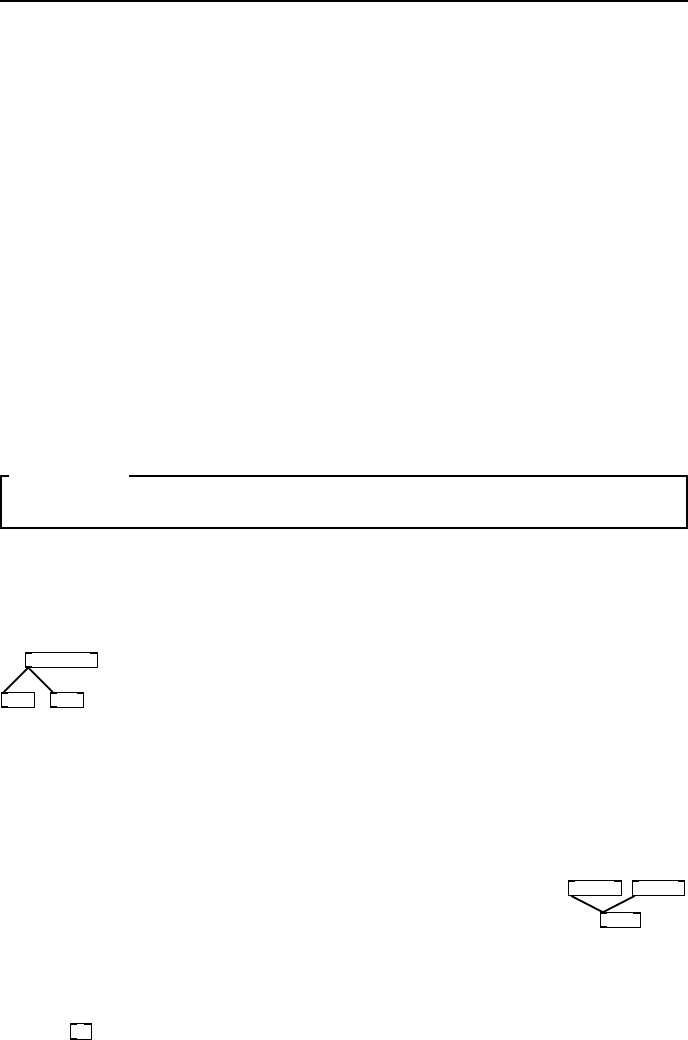
Blo cks
The signal data travelling down audio cords is made of samples,singlefloating
point values in a sequence that forms an audio signal. Samplesaregrouped
together in blocks.
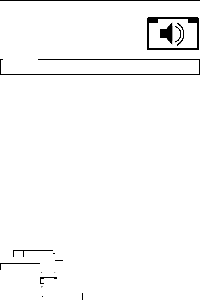
+~
31.4 15.9 26.5 35.8
97.9 42.3 84.6 26.4
B
1
B
2
B
3
B
4
A
1
A
2
A
3
A
4
129.3 58.2 111.1 62.2
+BA+BA
1
+B
1
A
22 33
A+B
44
Object Box
Inlet
Wire
Signal Block
fig 4.1: Object processing data.
Ablock,sometimesalsocalledavector,typ-
ically has 64 samples inside it, but you can
change this in certain circumstances. Ob-
jects operating on signal blocks behave like
ordinary message objects, they can add, sub-
tract, delay or store blocks of data, but do
so by processing o ne whole block at a time.
In Fig. 4.1 streams of blocks are fed to the
two inlets. Blocks appearing at the outlet
have values which are the sum of the cor-
responding values in the two input blocks.
Because they process signals made o f blocks, audio objects doalotmorework
than objects that process messages.
40 Pure Data Audio
Audio object CPU use
All the message objects we looked at in the last chapters only us e CPU when
event driven dataflow occurs, so most of the time they sit idle and consume
no resources. Many of the boxes we put on our sound design canvases will b e
audio objects, so it’s worth noting that they use up some CPU power just being
idle. Whenever compute audio is switched on they are processing a constant
stream of signal blocks, even if the blocks o nly contain zeros. Unlike messages
which ar e processe d in logical time, signals are processed synchro nously with
the soundcard sample rate. This real-time constraint means glitches will occur
unless every signal object in the patch can be computed beforethenextblock
is sent out. Pd will not simply give up when this happens, it will struggle
along trying to maintain real-time processing, so you need tolistencarefully,
as you hit the CPU limit of the computer you may hear crackles orpops. Itis
also worth knowing how audio computation relates to messagescomputation.
Messages operations are executed at the beginning of each pass of audio block
processing, so a patch where audio depends on message opera tions which don’t
complete in time will also fail to produce correct output.
SECTION 4.2
Audio objects and principles
There are a few ways that audio objects differ from message objects s o let’s
look at those rules now before starting to create sounds.
Fanout and merging
phasor~ 440
wrap~ *~ -1
fig 4.2: Sig-
nal fanout is
Okay.
You can connect the same signal outlet to as many other audio
signal inlets as you like, and blocks are sent in an order which
corresponds to the creation of the connections, much like message
connections. But unlike messages, most of the time this will have
no effect whatsoever, so you can treat audio signals that fan out
as if they were perfect simultaneous copies. Very seldom you may
meet rare and interesting problems, especially with delays and feedback, that
can be fixed by reordering audio signals (see Chapter 7 of Puckette, “Theory
and technique” regarding time shifts and block delays).
osc~ 120 osc~ 240
*~ 0.5
fig 4.3: Merg-
ing signals is
Okay.
When several signal connections all come into the same
signal inlet that’s also fine. In this ca se they are implicitly
summed, so you may need to scale your signal to reduce its
range again at the output of the object. You can connect as
many signals to the same inlet as you like, but sometimes it
makes a patch easier to understand if you explicitly sum them
with a
+~
unit.
Time and resolution
Time is measured in seconds, milliseconds (one thousandth ofasecond,writ-
ten 1ms) or samples. Most Pd times are in ms. Where time is measured in

4.2 Audio objects and principles 41
samples this depends on the sa mpling rate o f the progr a m or thesoundcardof
the computer system on which it runs. The current sample rate is returned by
the
samplerate~
object. Typically a sample is 1/44100th of a second and is the
smallest unit of time that can be measured a s a signal. But the time resolution
also depends on the object doing the computation. For example
metro
and
vline~
are able to deal in fractions of a millisecond, even less than one sample. Tim-
ing irregularities can occur where some objects are only accurate to one block
boundary and some are not.
Audio signal blo ck to messages
To see the contents of a signal block we can take a snapshot or anaverage.The
env~
object provides the RMS value of one blo ck of audio data scaled0to100
in dB, while
snapshot~
gives the instantaneous value of the last sample in the
previous block. To view an entire block for debugging
print~
can be used. It
accepts an audio signal and a bang message on the same inlet andprintsthe
current audio block contents when banged.
Sending and receiving audio signals
Audio equivalents of
send
and
receive
are written
send~
and
receive~
,with
shortened forms
s~
and
r~
.Unlikemessagesendsonlyoneaudiosendcan
exist with a given name. If you want to cr eate a signal bus with many to one
connectivity use
throw~
and
catch~
instead. Within subpatches and abstractions
we use the signal objects
inlet~
and
outlet~
to create inlets and outlets.
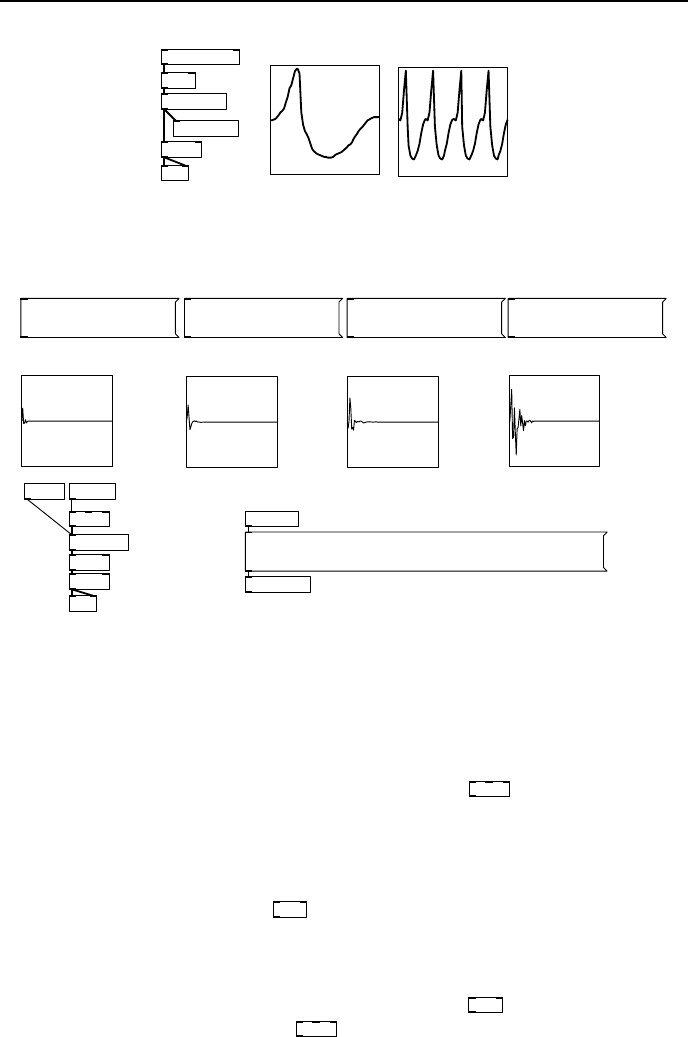
Audio generators
Only a few objects are signal sources. The most important and simple one is
the
phasor~
.Thisoutputsanasymmetricalperiodicrampwaveandisusedat
the heart of man y other digital oscillators we are going to make. Its left inlet
specifies the frequency in Hz, and its right inlet sets the phase, b etween 0.0and
1.0. The first and only argument is for frequency, so a typical instance of a
phasor looks like
phasor~ 110
.Forsinusoidalwaveformswecanuse
osc~
.Again,
frequency and phase are set by the left and right inlets, or frequency is set by
the creation parameter. A sinusoidal oscillator at concert Apitchisdefinedby
osc~ 440
.Whitenoiseisanothercommonlyusedsourceinsounddesign.The
noise genera tor in Pd is simply
noise~
and has no creation arguments. Its output
is in the range −1.0to1.0. Lo oped waveforms stored in an array can be used
to implement wavetable synthesis using the
tabosc4~
object. This is a 4 p oint
interpolating table ocillator and requires an array that is apowerof2,plus3
(eg. 0 to 258) in order to work properly. It can be instantiatedlike
phasor~
or
osc~
with a frequency argument. A table oscillator running a t 3kHzisshownin
Fig. 4.4. It takes the waveform stored in array A and loops around this at the
frequency given by its argument or left inlet value. To make sound samplers
we need to read and write audio data from an array . The index to
tabread~
and
its interpolating friend
tabread4~
is a sample number, so you need to supply a
signal with the correct slope and magnitude to get the proper playback rate.
You can use the special set message to reassign
tabread4~
to read from another
42 Pure Data Audio
*~ 64
tabread~ A
tabsend~ B
phasor~ 3000
dac~
*~ 0.1
B
A
fig 4.4: Table oscillator
kit1-01
loadbang
soundfiler
hip~ 5
r phase
vline~
kit1-02 kit1-03
kit1-04
r snum
tabread4~
;
snum set kit1-01;
phase 1, 4.41e+08 1e+07;
;
snum set kit1-02;
phase 1, 4.41e+08 1e+07;
;
snum set kit1-03;
phase 1, 4.41e+08 1e+07;
;
snum set kit1-04;
phase 1, 4.41e+08 1e+07;
dac~
*~ 0.5
read ./sounds/ttsnr.wav kit1-01, read ./sounds/jrsnr.wav
kit1-02, read ./sounds/dlsnr.wav kit1-03, read
./sounds/ezsnr.wav kit1-04
fig 4.5: Sample replay from arrays
array. The message boxes in Fig. 4.5 allow a single object to play back from
more than one sample table. First the target array is given viaamessageto
snum,andthenamessageissenttophase which sets
vline~
moving up at 44100
samples per second. The arrays are initially loaded, using a multi-part message,
from a sounds folder in the current patch directory.
Audio line objects
For signal rate control data the
line~
object is useful. It is generally programmed
with a sequence of lists. Each list consists of a pair of numbers, the first b eing a
level to move to and the second number is the time in milliseconds to take getting
there. The range is usually between 1.0and0.0whenusedasanaudiocontrol
signal, but it can be any value such as when using
line~
to index a table. A
more versatile line object is called
vline~
,whichwewillmeetinmuchmoredetail
later. Amongst its a dvantages are very accurate sub- millisecond timing and the
ability to read multi-segment lists in one go and to delay stages of movement.
Both these objects are essential for constructing envelope generators and other
control signa ls .
4.2 Audio objects and principles 43
Audio input and output
Audio IO is achieved with the
adc~
and
dac~
objects. By default these offer two
inlets or outlets for stereo operation, but you can request asmanyadditional
sound channels as your sound system will handle by giving themnumerical
arguments.
Example: A simple MIDI monosynth
notein
stripnote
mtof
osc~ vline~
*~
dac~
/ 127
*~
0, 1 10 0, 0 100 20
t f b
fig 4.6: MIDI note
control
Using the objects we’ve just discussed let’s create a little
MIDI keyboard controlled music synthesiser as shown in
Fig. 4.6. Numbers appearing at the left outlet of
notein
control the frequency of an oscillator . MIDI numbers
are converted to a Hertz frequency by
mtof
.TheMIDI
standard, or rather general adherence to it, is a bit woolly
by allowing note-off to also be a note-on with a velocit y of
zero. Pd follows this definition, so when a key is released
it produces a note with a zero velocity. For this simple
example we remove it with
stripnote
,whichonlypasses
note-on messages when their velocity is greater than zero.
The velocity value, ranging between 1 and 127 is scaled to between 0 and 1 in
order to provide a rudimentary amplitude control.
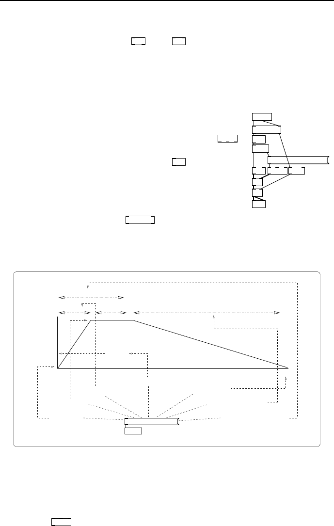
0, 1 10 0, 0 100 20
vline~
Time
Level
start at zero
move to 1
in 10 milliseconds
after a 0 millisecond delay
after a 20 millisecond delay
taking 100 milliseconds
return to zero
100ms
10ms10ms
20ms
at zero
so really start
fig 4.7: Anatomy of vline message
So, here’s a great place to elaborate on the anatomy of the message used
to control
vline~
as shown in Fig. 4.7. The syntax makes perfect sense, but
sometimes it’s hard to visualise without practice. The general form has three
numbers per list. It says: “go to some value”,givenbythefirstnumber,then

44 Pure Data Audio
“take a certain time to get there”,whichisthesecondnumberineachlist. The
last number in the list is a time to wait before executing the command, so it
adds an extra wait for a time before doing it”.Whatmakes
vline~
cool is you
can send a sequence of list messages in any order, and so long astheymake
temporal sense then
vline~
will ex e c ute them all. This means you can make
very complex control envelopes. Any missing arguments in a list are dropped
in right to left order, so a valid exception is seen in the first element of Fig. 4.7
where a single 0 means “jump immediately to zero” (don’t bother to wait or
take any time getting there).
Audio filter objects
Six or seven filter s are used in this book. We will not look a t them in much
detail until we need to because there is a lot to say about theirusageineach
case. Simple one pole and one zero real filters are given by
rpole~
and
rzero~
.
Complex one pole and one zero filters are
cpole~
and
czero~
.Astaticbiquad
filter
biquad~
also comes with a selection of helper objects to calculate coefficients
for common configurations and
lop~
,
hip~
,and
bp~ 1
provide the standard low,
high and bandpass responses. These are easy to use and allow message rate
control of their cutoff frequencies and, in the case of bandpass, resonance. The
first and only argument of the low and high pass filters is freq uency, so typical
instances may look like
lop~ 500
and
hip~ 500
.Bandpasstakesasecondparameter
for r e sonance like this
bp~ 100 3
.Fastsignalratecontrolofcutoff is possible using
the versatile
vcf~
“voltage controlled filter”. Its first argument is cutoff frequency
and its second argument is resonance, so you might use it like
vcf~ 100 2
.With
high resonances this provides a sharp filter that can give narrow bands. An
even more colour ful filter for use in music synthesiser designs is available as an
external called
moog~
,whichprovidesaclassicdesignthatcanselfoscillate.
Audio arit hmetic objects
Audio signal objects for simple arithmetic are summarised inTbl.4.8.
Object Function
+~
Add two signals (either input will also accept a message)
-~
Subtract rightha nd signal from lefthand signal
/~
Divide lefthand signal by right signal
*~
Signal multiplication
wrap~
Signal wrap, constrain any signal between 0.0and1.0
fig 4.8: List of arithmetic operators
Trigonometric and math ob jects
AsummaryofhighermathsfunctionsisgiveninTbl.4.9. Somesignal units
are abstractions defined in terms of more elementary intrinsic objects and those
marked * are only available through external libraries in some Pd versions.

4.2 Audio objects and principles 45
Object Function
cos~
Signal version of cosine function. Domain: −1.0 to +
1.0. Note the input domain is “rotation normalised”
sin~
Not intr i nsic but defined in terms of signal cosine by
subtracting 0.25 from the input.
atan~
* Signal version of arctangent with normalised range.
log~
Signal version of natural log.
abs~
* Signal version of abs.
sqrt~
Asquarerootforsignals.
q8_sqrt~
Afastsquarerootwithlessaccuracy.
pow~
Signal version of power function.
fig 4.9: List of tri g and higher math operators
Audio delay objects
Delaying an audio signal requires us to create a memory buffer using
delwrite~
.
Two arguments must be supplied at creation time, a unique nameforthemem-
ory buffer and a ma ximum size in milliseconds. For example,
delwrite~ mydelay 500
creates a named delay buffer “mydelay” of size 500ms. This object can now
be used to write audio data to the delay buffer through its left inlet. Getting
delayed signals back from a buffer needs
delread~
.Theonlyargumentneededis
the name of a buffer to read from, so
delread~ mydelay
will listen to the contents of
mydelay.Thedelaytimeissetbyasecondargument,orbytheleftinlet. It
can range from zero to the maximum buffer size. Setting a delay time larger
than the buffer results in a delay of the maximum size. It is not possible to
alter the maximum size of a
delwrite~
buffer once created. But it is possible to
change the delay time of
delread~
for chorus and other effects. This often results
in clicks and pops
1
so we have a
vd~
variable-delay object. Instead of moving
the read point
vd~
changes the rate it reads the buffer, so we get tape echo and
Doppler shift type effects. Using
vd~
is as easy as before, create an object that
reads from a named buffer like
vd~ mydelay
.Theleftinlet(orargumentfollowing
the name) sets the delay time.
1
Hearing clicks when moving a delay read point is normal, not a bug. There is no reason
to assume that wavforms will align nicely once we jump to a new location in the buffer. An
advanced solution crossfades between more than one buffer.
